Bosch Security Systems | 2011-02
2011-02 | Installation and User Instructions | 5 | Call Stations en | 258
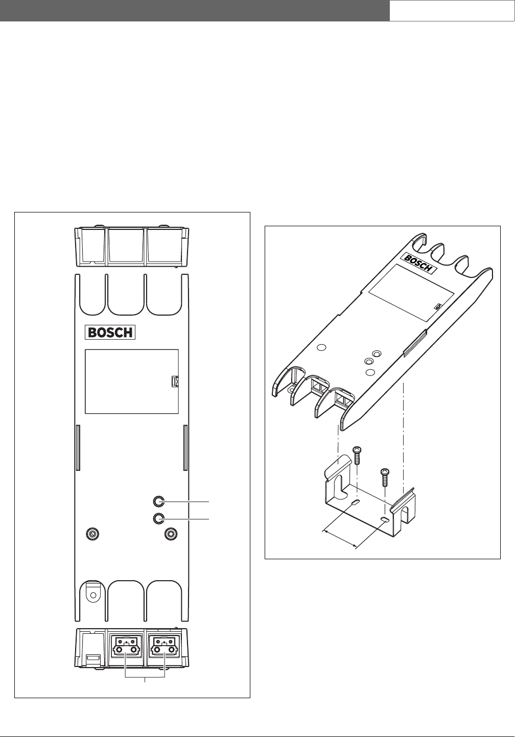
23.2 Controls and indicators
The call stacker (see figure 23.2) contains the following:
1 Fault LED - A yellow fault LED that provides
information about the status of the call stacker (see
section 23.5).
2 Power LED - A green power LED that provides
information about the status of the call stacker (see
section 23.5).
3 System bus - Two system bus connectors to
connect the call stacker to other Praesideo
equipment (see section 23.3.1).
23.3 Connections
23.3.1 Connecting the network
Connect the call stacker to the Praesideo system using
the system bus connectors and LBB4416 network
cables. Both connectors are interchangeable.
23.4 Installation
The call stacker can be attached to a wall or any other
flat surface using a bracket (seefigure 22.3). The distance
(d) between the holes in the bracket is 40 mm.
Mounting of this bracket and the unit on a drywall sheet
construction requires screws with a minimum screw
length of 22 mm (7/8") and a minimum diameter of
2.5 mm (3/32"). Mounting was evaluated for use on a
drywall surface only.
figure 23.2: Exterior
3
1
2
figure 23.3: Installation
d


