


Bosch Security Systems | 2011-02
2011-02 | Installation and User Instructions | 5 | Call Stations en | 228
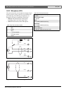
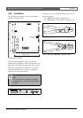
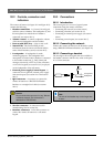
19.2.1 Control inputs (X800)
The external interface for control inputs consists of a pin
header connector with 20 positions (see the PCB for the
pin numbering). These control inputs cannot be
supervised.
19.2.2 Control outputs (X810)
The external interface for control outputs consists of a
pin header connector with 40 positions (see the PCB for
the pin numbering).
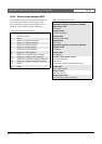
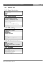
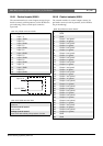
table 19.1: X800 connector details
Pin Signal
1 Input 1, in
2 Input 1, GND
3 Input 2, in
4 Input 2, GND
5 Input 3, in
6 Input 3, GND
7 Input 4, in
8 Input 4, GND
9 Input 5, in
10 Input 5, GND
11 I npu t 6 , in
12 Input 6, GND
13 Input 7, in
14 Input 7, GND
15 Input 8, in
16 Input 8, GND
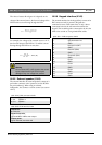
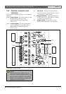
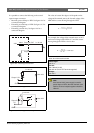
figure 19.3: Input connection diagram
table 19.2: X800 technical data
Cable length:
max. 5 m
Current (control inputs):
max. 0.5 mA
Voltage (control inputs):
max. 3.3 V with internal pull-up resistor of 10 kΩ
Input X, GND
Input X, IN
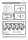
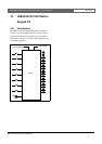
table 19.3: X810 connector details
Pin Signal
1GND
2 GND
3 Output 1, out (green)
4 Output 1, in (green)
5 Output 2, out (green)
6 Output 2, in (green)
7 Output 3, out (green)
8 Output 3, in (green)
9 Output 4, out (green)
10 Output 4, in (green)
11 Output 5, out (green)
12 Output 5, in (green)
13 Output 6, out (green)
14 Output 6, in (green)
15 Output 7, out (green)
16 Output 7, in (green)
17 Output 8, out (green)
18 Output 8, in (green)
19 Output 1, out (yellow)
20 Output 1, in (yellow)
21 Output 2, out (yellow)
22 Output 2, in (yellow)
23 Output 3, out (yellow)
24 Output 3, in (yellow)
25 Output 4, out (yellow)
26 Output 4, in (yellow)
27 Output 5, out (yellow)
28 Output 5, in (yellow)
29 Output 6, out (yellow)
30 Output 6, in (yellow)
31 Output 7, out (yellow)
32 Output 7, in (yellow)
33 Output 8, out (yellow)
34 Output 8, in (yellow)
35 GND
36 GND