


Bosch Security Systems | 2011-02
Praesideo 3.5 | Installation and User Instructions | 12 | Appendices en | 493
B Kycon KPP-4P connector
B.1 Introduction
This appendix contains assembly instructions and a
connection diagram for the Kycon KPP-4P connector
that is used to connect the PRS-NSP Network Splitter,
the PRS-FIN(S), PRS-FINNA Fiber Interface, the PRS-
CSR Remote Control Station and the PRS-CSI Call
Station Interface to power supplies.
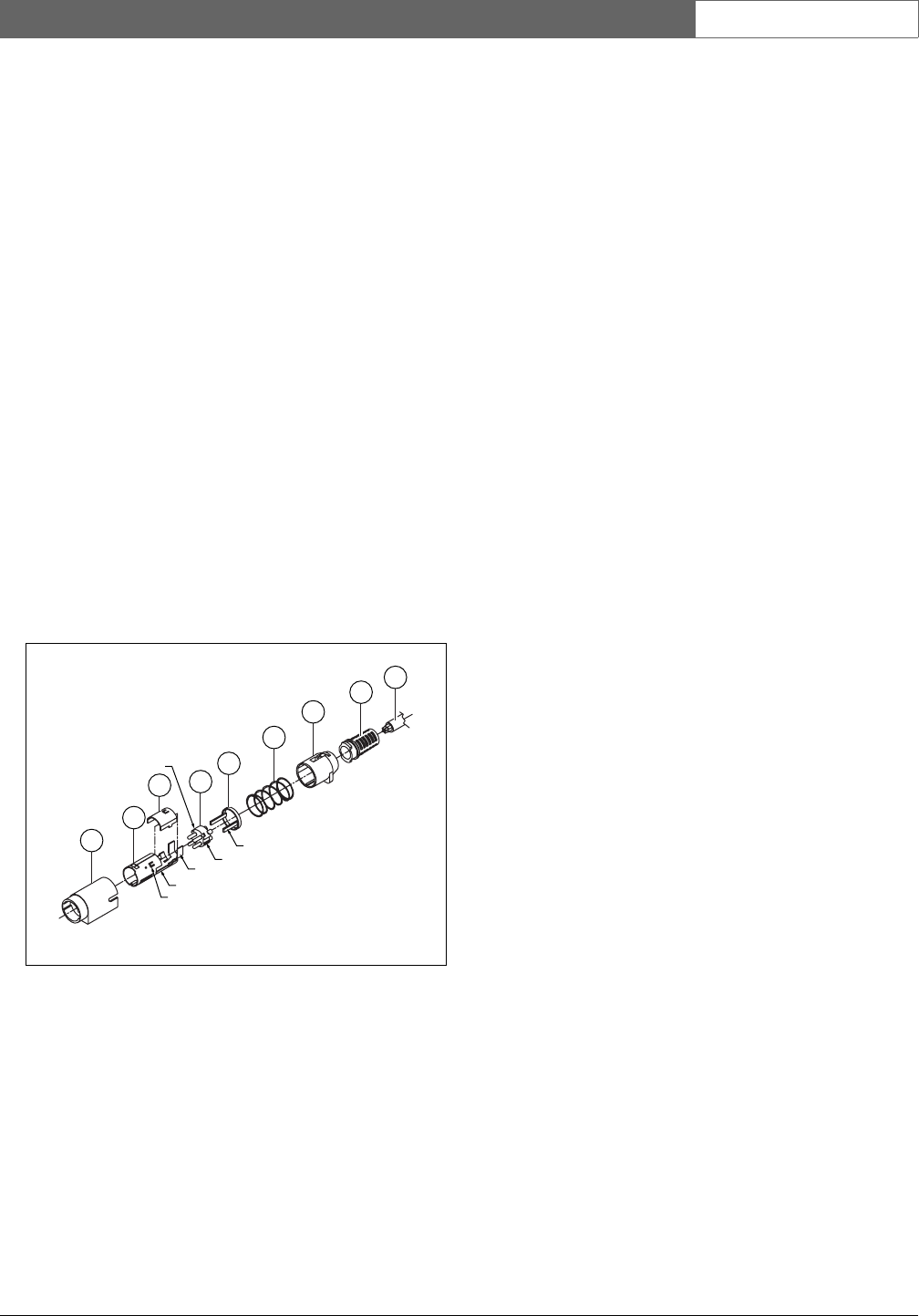
B.2 Assembly
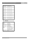
The connector consists of the following (see figure B.1):
A Customer Cable
BStrain Relief
C Plastic Enclosure
DMetal Spring
E Plastic Guide
F Top Metal Cover
G Pin Mold
H Lower Metal Sleeve
I Plastic Coupling
Proceed as follows to assembly a Kycon KPP-4P
connector:
1 Attach Strain Relief (B) to Plastic Enclosure (C).
2 Pass Cable (A) through Strain Relief (B)/Plastic
Enclosure (C) assembly, Metal Spring (D) and Plastic
Guide Ring (E).
3 Solder cable wires to solder cups on Pin Mold (G).
4 Properly align Pin Mold (G) with Lower Metal
Sleeve (H). The slotted sections on the sides of the
Pin Mold (G) must line up with the slotted cut-outs
on the Lower Metal Sleeve (H) and the 3 semi-
circular notches around the perimeter of the Pin
Mold (G) must line up with the 3 metal tabs inside
the Lower Metal Sleeve (H).
5 Push Pin Mold (G) forward into the Lower Metal
Sleeve (H) until it locks into place.
6 Manually press the 3 metal tabs on the Lower Metal
Sleeve (H) into the notches in the Pin Mold (G).
7 Crimp 'U' section of Lower Metal Sleeve (H) onto
Cable (A).
8 Fit Plastic Ring Guide (E) into Lower Metal Sleeve
(H) by placing plastic arms into the appropriate slots
on the sides of the sleeve.
9 Attach Top Metal Cover (F) onto Lower Metal Sleeve
(H). Be sure to align all tabs and securely install
cover.
10 Push Metal Spring (D) onto the Top Metal Cover (F)/
Lower Metal Sleeve (H) assembly. This will help to
hold the assembly together.
11 Push Strain Relief (B)/Plastic Enclosure (C) assembly
onto the Top Metal Cover (F)/Lower Metal Sleeve
(H) assembly. The two assemblies must be properly
aligned as shown in the drawing. Be sure to check
that the Metal Spring (D) remains in place and does
not go underneath either the Plastic Enclosure (C) or
the Plastic Guide (E) or twists during assembly. A
significant amount of force may be necessary to lock
the two assemblies together.
12 Check to make sure that the Strain Relief (B)/Plastic
Enclosure (C) assembly is securely locked into place
over the Top Metal Cover (F)/Lower Metal Sleeve
(H) assembly. The two assemblies should not be able
to be pulled apart.
13 Properly align the new assembly with the Plastic
Coupling (I) as shown in the drawing. Push assembly
into Plastic Coupling (I) until it locks properly into
place. The entire plug assembly is now complete.
figure B.1: Assembly drawing
A
B
C
D
E
G
F
semi-circular notch
arm
H
I
slot
slotted cut-out
metal tabs
'U' section