


Bosch Security Systems | 2011-02
2011-02 | Installation and User Instructions | 5 | Call Stations en | 251
22.2 Controls, connectors and
indicators
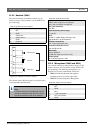
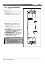
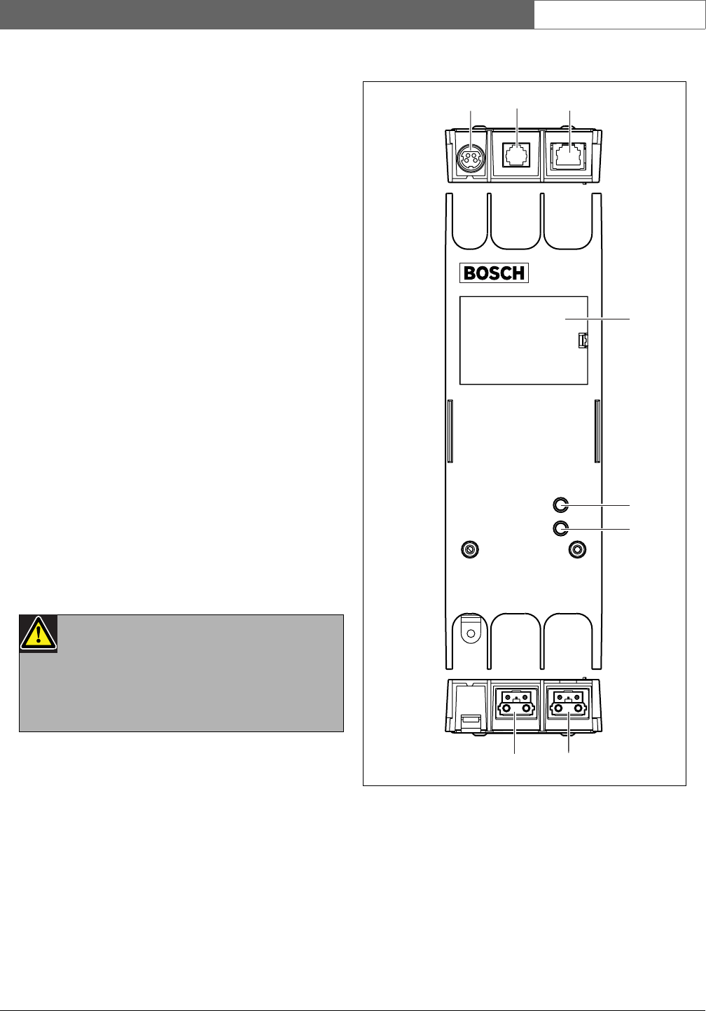
22.2.1 Exterior
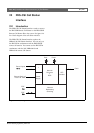
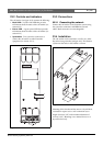
The exterior of the call station interface (see figure 22.2)
contains the following:
1 System bus - A system bus connector to connect
the call station interface to other Praesideo
equipment (see section 22.3.2).
2 System bus - A system bus connector to connect
the call station interface to other Praesideo
equipment (see section 22.3.2).
3 Lid - A lid that provides access to the jumpers (see
section 22.2.2). The rear side of the lid contains a
label with explanation about the internal settings.
4 Fault LED - A yellow fault LED that provides
information about the status of the call station
interface (see section 22.5).
5 Power LED - A green power LED that provides
information about the status of the call station
interface (see section 22.5).
6 RJ45 connector - A connector to connect the call
station interface to a PRS-CSR Remote Call Station
or PRS-CSRK Remote Call Station Kit.
7 External power supply - A connection for an
(optional) external power supply (see section 22.3.3).
8 Service connector - A connector used for
manufacturing. Not for normal use.
Caution
Do not connect the connections 6 and 8 to any
Telecom or Ethernet network. These
connections are dedicated for PRS-CSR or
PRS-CSRK and service equipment.
figure 22.2: Exterior
1
2
6
7
4
3
5
8