


Bosch Security Systems | 2011-02
2011-02 | Installation and User Instructions | 5 | Call Stations en | 229
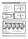
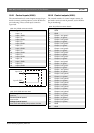
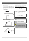
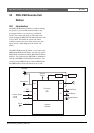
It is possible to connect the following to the control
inputs/outputs connector:
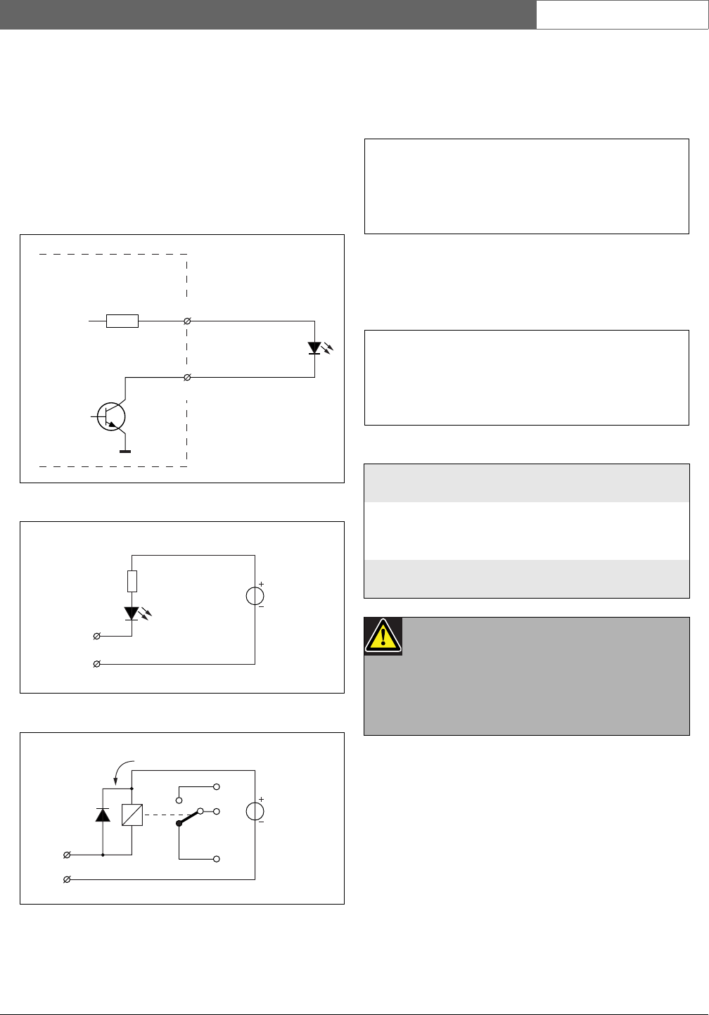
• Internally powered lamp or LED. See figure 19.4 for
a connection diagram.
• Externally powered lamp or LED. See figure 19.5 for
a connection diagram.
• Externally powered relay. See figure 19.6 for a
connection diagram.
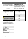
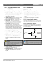
The value of resistor R in figure 19.5 depends on the
voltage of the external source, the forward voltage of the
LED and the current flowing through the LED:
For example, the voltage of the external source is 24 V,
the forward voltage of the LED is 2 V and the current
flowing through the LED is 10 mA, then:
figure 19.4: Internally powered LED
figure 19.5: Externally powered LED
figure 19.6: Externally powered relay
3.3V
Output X, OUT
I < 22 mA
Output X, IN
150 Ω
Max. 30V
Output X, IN
R
GND
I < 100 mA
Max. 30V
I < 100 mA
Output X,
IN
GND
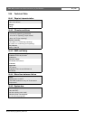
table 19.4: X810 technical data
Cable length:
max. 5 m
Current:
max. 100mA (via IN)
max. 64 mA (via all OUT terminals together)
Voltage:
max. 30 V
Note
If the internal 3.3 V power supply is used to
power lamps or LEDs, then the maximum total
load for all control outputs together should be
<64 mA.
R
V
source
V
forward
–
I
---------------------------------------------=
R
24 2–
10 10
3–
⋅
--------------------- 2 2 00 Ω()==