


Emerson Process Management GmbH & Co. OHG 1-27
X-STREAM X2
Instruction Manual
HASX2E-IM-HS
02/2012
1.8 X-STREAM X2FD
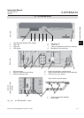
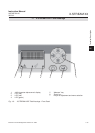
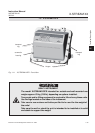
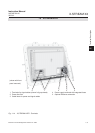
1.8 X-STREAM X2FD: Cast Aluminum Flameproof Housing
The most obvious X-STREAM 2FD analyzer
feature is its ameproof housing (Fig. 1-10).
This enables its use in Ex-zone 1 hazardous
environments. With its protection type of IP66/
NEMA 4X and sturdy cast aluminum housing
designed for wall-mounting, it can also be
used in other tough environments.
IPx6: In case of occasional ooding, e.g.
heavy seas, water shall not enter in harmful
quantities
IP6x: Protection against penetration by dust.
Live or internal moving parts are completely
protected.
Up to four measuring channels in any com-
bination can be installed in the X-STREAM
X2FD. Optionally, a cover can be installed
over the physical components. This separa-
te volume can be heated up to a maximum
temperature of 60 °C to minimize the effects
of changes in external temperature.
A description of the different piping options is
given in
section 1.2.6, page 1-5.
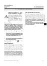
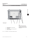
Front panel
The front panel is physically protected with
a safety glass panel and consists of a 4x20-
character alphanumeric LC display, a keypad
and 3 status LEDs (Fig. 1-11). The colors of
the LEDs are based on the NAMUR NE 44
specications
. The LEDs are activated in line
with NE 107 standards and indicate “Failure”,
“Function check”, “Out of specication” and
“Maintenance request”.
Instead of the LCD
display, a vacuum uorescent display can
be tted.
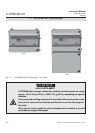
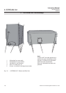
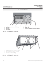
Electrical connections
Electrical connections are made via internal
screw-type terminals; the corresponding
cables are fed through cable inlets on the
underside of the unit into the housing (Fig.
1-12). The front of the unit opens downwards
once the screws located on the surrounding
ange are removed
.
Power supply
Mains power is connected via screw-type
terminals with integrated fuses, located in
the front right-hand area of the housing. The
internally mounted wide range power sup-
ply unit ensures the analyzers can be used
worldwide.
Interface signals
In the basic conguration, the unit has 36
internal screw-type terminals for interface
signals, providing one analog output (4–20 or
0–20 mA) for each channel and the contacts
for the four NAMUR status relays. Further
DANGER OF EXPLOSION
The special conditions for installing and operating analyzers in hazardous
areas are not covered by this manual!
Read the separate instruction manuals shipped together with instrument
intended to be installed in hazardous area!
1
Technical Description