


Emerson Process Management GmbH & Co. OHG 1-5
X-STREAM X2
Instruction Manual
HASX2E-IM-HS
02/2012
1.2 Conguration of Gas Lines
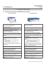
1.2.6 Optional Components for Gas Lines
The analyzers can, as an option, be tted with
further components. Not all components are
available for all analyzer types:
• internal sample gas pump
• internal valve block
• internal ow sensors
• internal ow monitor switch
• internal barometric pressure meters
• internal temperature sensors.
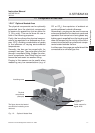
1.2.6.1 Internal Sample Gas Pump
An internal sample gas pump is used when
the sample gas is under insufcient pressure.
It ensures a constant ow of sample gas (max.
2.5 l/min through the analyzer).
When in internal pump is tted, the relevant
parameter in the software setup dialog is set
to Yes ( 6.2.3.5, page 6-43). The pump
can be controlled either manually through a
software menu or optionally by a digital input.
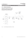
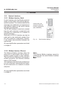
1.2.6.2 Internal Valve Block
The use of an internal valve block allows all
necessary gas lines (zero gas, span gas,
sample gas) to remain permanently connec-
ted to the analyzer. Valves are then activated
automatically when required (e.g. during au-
tomatic calibration).
When an internal valve block is tted, this is
shown in the relevant software setup dialog
as either Internal or Int+Ext (
6.2.3.5,
page 6-43). The valves are controlled by
either a software menu, optionally by digital
input, or automatically during autocalibration.
Depending on the model, up to two valve
bocks can be tted.
1.2.6.3 Internal Flow Sensor
Up to two internal ow sensors can measure
the ow of gas and can activate an alarm si-
gnal in the event of a failure. The alarm level
for ow sensors is operator adjustable to up
to 2000 ml/min. Depending on the model, up
to two sensors can be tted and evaluated
separately.
When a sensor is tted, the relevant parame-
ter in the software setup dialog is set to Yes
(
6.2.3.5, page 6-43).
If the current ow rate is too low, a status
message is displayed and the parameter
under CHECK REQUESTS.. is set to Yes
( Chapter 8 “Troubleshooting”).
1.2.6.4 Internal Flow Monitor Switch
An internal ow switch monitors the gas ow
and activates an alarm signal in case it is not
sufcient. The alarm level for the internal ow
switch is xed and not operator adjustable.
Additional external switches may used and
connected via digital inputs. All tted ow
switches are evaluated to share a common
alarm.
When an internal ow switch is tted, the re-
levant parameter in the software setup dialog
is set to Yes (
6.2.3.5, page 6-43).
If the current ow rate is too low, a status
message is displayed and the parameter
under CHECK REQUESTS.. is set to Yes
( Chapter 8 “Troubleshooting”).
1
Technical Description