


Emerson Process Management GmbH & Co. OHG 1-17
X-STREAM X2
Instruction Manual
HASX2E-IM-HS
02/2012
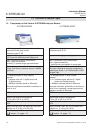
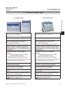
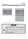
1.6 X-STREAM X2GP: 19 Inch Table-Top or Rackmount Design
1.6 X-STREAM X2GP
This model can be fitted with up to four
measurement channels in any combination.
The physical components can optionally be
encased in a cover. This area can be held at
a specic temperature of up to 60 °C to mi-
nimize interference from changes in external
temperature.
Units congured for rack mounting can be
converted for tabletop use by removing the
lateral mounting brackets and attaching the
four feet supplied as accessories.
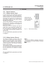
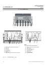
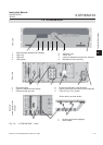
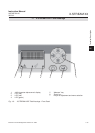
Front panel
The analyzer’s front panel consists of one
4x20-character alphanumeric LC display, a
membrane keyboard and three status LEDs
(Fig. 1-5). The colors of the LEDs are based on
the NAMUR NE 44 specications. The LEDs
are activated according to the NE 107 stan-
dards and correspond to the following ststus
messages: “Failure”, “Function check”, “Out of
specication” and “Maintenance request”.
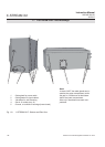
Connection to power supply
Main power is supplied via the IEC chassis
plug mounted on the rear panel, with inte-
grated power switch and fuse holders. The
internal wide range power supply unit enables
the analyzers to be used worldwide.
Interfaces
Electrical connections for interface signals
are provided via the submin-D connectors
also mounted on the rear panel of the device
(Fig.1-5).
For applications where screw-type terminals
are preferred for connecting signal wires, op-
tional adapters are available, which are moun-
ted directly onto the submin-D connectors.
Interface signals
The number of connections varies according
to the number of interfaces installed: a 25-
pin submin-D socket terminal strip is always
included, providing one analog output (4-20
or 0-20 mA) and the contacts for the four
(NAMUR) status relays. Further analog out-
puts can also be provided, e.g. to provide a
measurement signal at different resolutions. A
maximum of four analog outputs is possible.
A serial Modbus interface can also be installed
on request (RS 232 or RS 485 with Modbus
RTU protocol, via 9-pin submin-D male conec-
tor
); alternatively an RJ45 socket can also
give access to Ethernet-Modbus-TCP.
Digital inputs and outputs can be used to
control analyzer functions and external
components. The 7 inputs and 9 outputs are
connected to peripheral devices via a 37-pole
sumbin-D socket terminal strip. The number of
digital inputs and outputs can be doubled (to
14 inputs and 18 outputs) by adding a second
card. The rst digital I/O card is marked "X4.1"
while the second is "X4.2" on the rear panel,
right above the connector (Fig. 1-5, rear view).
Detailed technical details on the various in-
terfaces can be found in
1.3, page 1-9.
The conguration of the connectors and the
optional screw-type terminal adapters is de-
scribed in chapter 4 “Installation” and the
software settings in chapter 6 “Software”.
A further submin-D socket, which is not de-
scribed in this manual, is also located at the
rear of the unit, and is designated as a Service
Interface.
1
Technical Description