


Emerson Process Management GmbH & Co. OHG 4-21
X-STREAM X2
Instruction Manual
HASX2E-IM-HS
02/2012
4
Installation
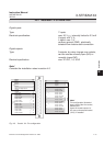
4.6.2 Installation - X-STREAM X2GP
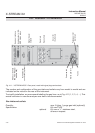
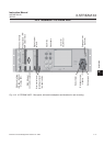
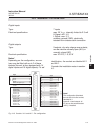
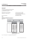
Fig. 4-16: Sockets X4.1 and X4.2 - Pin conguration
Digital inputs
Type: 9 outputs, dry relay change-over ontacts,
can be used as normally open (NO) or
normally closed (NC)
Electrical specication: max. 30 VDC, 1 A, 30 W
Type: 7 inputs
Electrical specication: max. 30 V , internally limited to 2.3 mA
H Signal: min. 4 V;
L Signal: max. 3 V
common ground (GND), electrically
isolated from chassis earth connection
Digital outputs
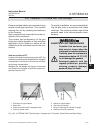
Notes!
Depending on the conguration, an ana-
lyzer may be tted with up to 2 of these
sockets (the unit is thus equipped with 14
digital inputs and 18 digital outputs). To aid
identication, the sockets are labelled X4.1
and X4.2.
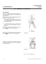
Consider the installation notes in section
4.5.
Signal Pin
Input 1 1
Input 2 2
Input 3 3
Input 4 4
GND for all digital inputs 5
unused 6
unused 7
Output 5 NC 8
Output 5 NO 9
Output 5 COM 10
Output 6, NC 11
Output 6, NO 12
Output 6, COM 13
Output 7, NC 14
Output 7, NO 15
Output 7, COM 16
Output 8, NC 17
Output 8, NO 18
Output 8, COM 19
Digital
outputs
Digital
inputs
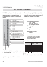
Pin Signal
20 Input 5
21 Input 6
22 Input 7
23 Output 9, NC
24 Output 9, NO
25 Output 9, COM
26 Output 10, NC
27 Output 10, NO
28 Output 10, COM
29 Output 11, NC
30 Output 11, NO
31 Output 11, COM
32 Output 12, NC
33 Output 12, NO
34 Output 12, COM
35 Output 13, NC
36 Output 13, NO
37 Output 13, COM
Digital
outputs
Digital
inputs
Note!
The conguration illustrated
here is that of the rst socket,
labelled X4.1.
Inputs 8-14 and outputs 14-
23, are on the second socket
(X4.2), if installed.