


Emerson Process Management GmbH & Co. OHG1-24
X-STREAM X2
Instruction Manual
HASX2E-IM-HS
02/2012
1.7 X-STREAM X2XF Field Housings
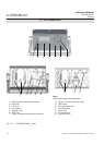
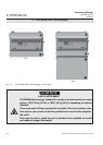
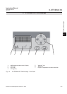
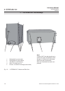
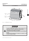
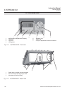
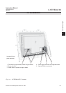
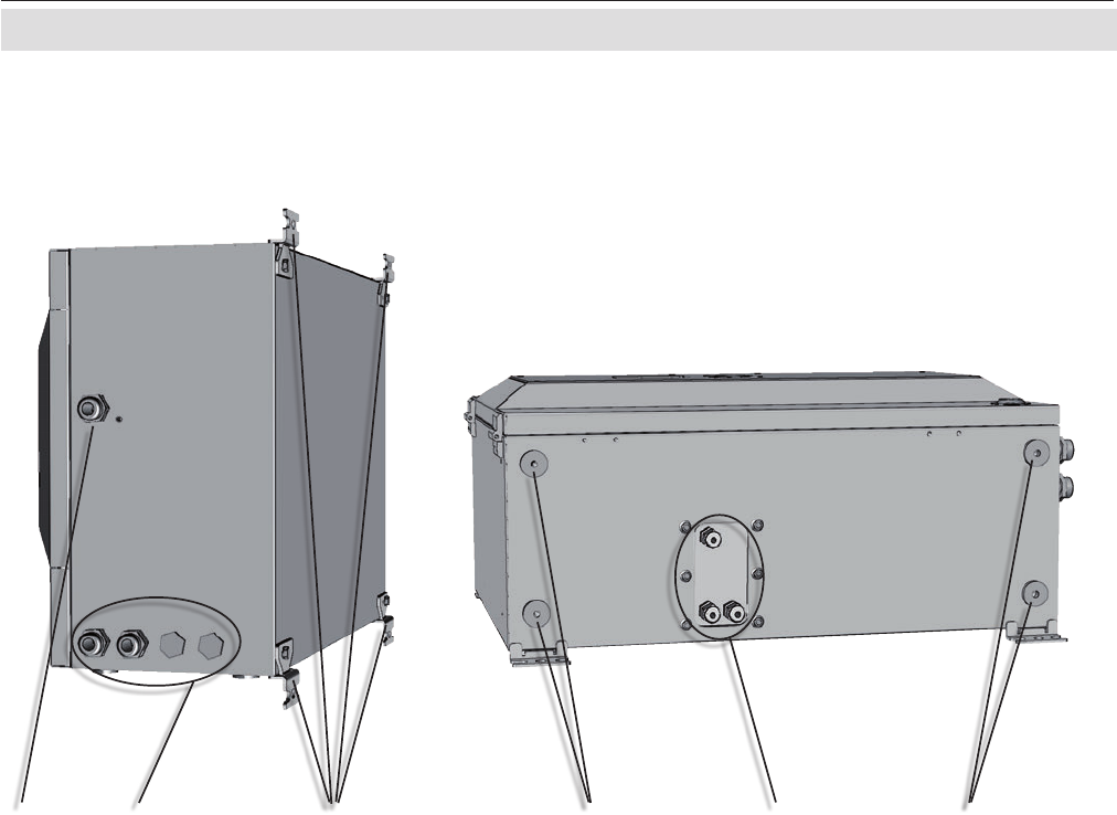
Fig. 1-9: X-STREAM XLF - Bottom and Side View
1 Cable gland for power cable
2 Cable glands for signal cables
3 4 brackets for wall-mounting
4 Gas in- & outlets (max. 8)
5 Cutouts, to combine 2 housings (here closed)
21 3 5 4 5
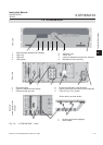
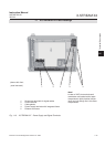
Note!
In case of XXF, the cable glands are lo-
cated at the upper compartment, while
the gas in- & outlets are at the bottom
side of the lower compartment.
Also only 2 brackets are at each com-
partment.