


Emerson Process Management GmbH & Co. OHG 7-51
X-STREAM X2
Instruction Manual
HASX2E-IM-HS
02/2012
7
Maintenance & Procedures
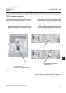
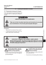
7.5.3.3 Adjusting the Output Signal
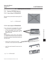
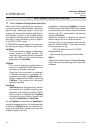
Fig. 7-14: Sensor At Rear Panel
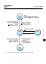
Fig. 7-15: OXS Board, Top View
Procedure:
• power on the open instrument.
• Supply ambient air (approx. 21 % O
2
)
• Connect a digital voltmeter (DVM) to
Tp 1 (signal) and Tp 2 (GND) on the elec-
tronics board OXS (g. 7-14).
• Adjust the measured signal to 3360 mV DC
(± 5 mV) utilizing the potentiometer R4 on
OXS board.
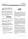
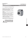
Having replaced the worn sensor, the board´s
output signal requires some adjustment.
Note!
Once the output signal has been adjusted
for a specic sensor, further changing the
potentiometer settings will cause incorrect
measuring results!
Strip P3 for sensor connection
Potentiometer R4
Tp 1
Tp 2
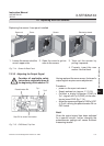
Consider all applicable safety
instructions, especially those at
the beginning of this section 7.5
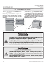
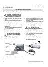
Replacing the sensor if rear panel installed
1. Loosen the screw nut at the
cover's upper side.
2. Open the cover to get ac-
cess to the sensor.
3. Take out the sensor by
pulling it upwards.
4. Properly insert the new
sensor into the block.
Sensor Electronics board
CoverScrew nut
7.5 Replacing Worn Out Sensors