


Emerson Process Management GmbH & Co. OHG 4-29
X-STREAM X2
Instruction Manual
HASX2E-IM-HS
02/2012
4
Installation
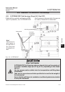
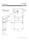
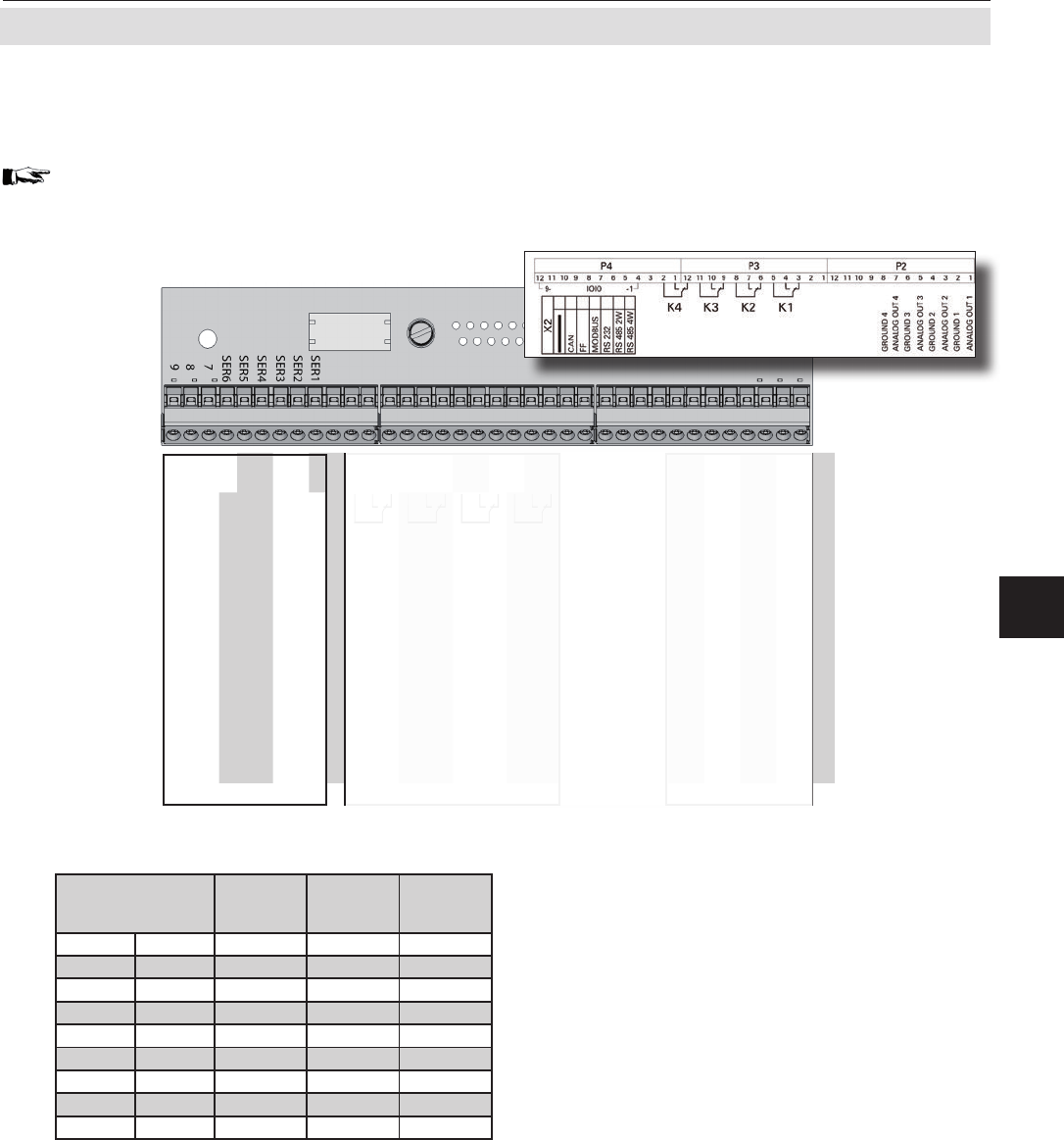
4.6.3 Installation - X-STREAM X2XF Field Housings
Modbus interface
Specication and interface control:
Chapter 9
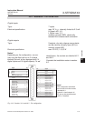
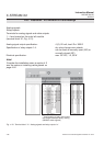
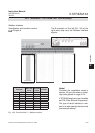
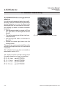
Fig. 4-22: Terminal block X1 - Modbus interface
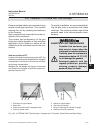
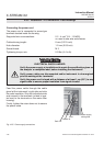
Notes!
Consider the installation notes in
section 4.5 and the notes on instal-
ling cable glands on page 4-24.
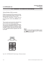
X-STREAM analyzers are classied
as DTE (Data Terminal Equipment).
The type of serial interface is mar-
ked on a label nearby the terminals
(see sample above)
The 9 terminals on the left (28 - 36) of the
right most strip carry the Modbus interface
signals.
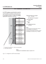
Pin Signal
P2.1 Channel 1, (+) 4 (0) - 20 mA
P2.2 Channel 1, GND
P2.3 Channel 2, (+) 4 (0) - 20 mA
P2.4 Channel 2, GND
P2.5 Channel 3, (+) 4 (0) - 20 mA
P2.6 Channel 3, GND
P2.7 Channel 4, (+) 4 (0) - 20 mA
P2.8 Channel 4, GND
P2.9 not used
P2.10 not used
P2.11 not used
P2.12 not used
P3.1 not used
P3.2 not used
P3.3 Output 1 (Failure), NC
P3.4 Output 1 (Failure), NO
P3.5 Output 1 (Failure), COM
P3.6 Output 2 (Maintenance Request), NC
P3.7 Output 2 (Maintenance Request), NO
P3.8 Output 2 (Maintenance Request), COM
P3.9 Output 3 (Function Contro), NC
P3.10 Output 3 (Function Contro), NO
P3.11 Output 3 (Function Contro), COM
P3.12 Output 4 (Out of Spec), NC
P4.1 Output 4 (Out of Spec), NO
P4.2 Output 4 (Out of Spec), COM
P4.3 not used
P4.4
P4.5
P4.6
P4.7
P4.8
P4.9
P4.10
P4.11
P4.12
Relay Outputs
**)
Analog Outputs
Serial Interface
*)
*)
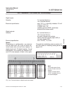
See table below
X
Terminal
MOD 485/
2 wire
MOD 485/
4 wire
RS 232
P4.4 SER1 Common Common Common
P4.5 SER2
not used not used
RXD
P4.6 SER3
not used not used
TXD
P4.7 SER4
not used
RXD1(+)
not used
P4.8 SER5 D1(+) TXD1(+) Common
P4.9 SER6
not used not used not used
P4.10 7
not used not used not used
P4.11 8
not used
RXD0(-)
not used
P4.12 9 D0(-) TXD0(-)
not used