


Emerson Process Management GmbH & Co. OHG1-20
X-STREAM X2
Instruction Manual
HASX2E-IM-HS
02/2012
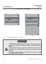
1.7 X-STREAM X2XF Field Housings
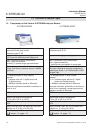
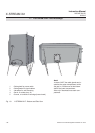
1.7 X-STREAM X2XF: Field Housing With (XLF) Single Or (XXF) Dual Compartment
Field housings are conceived for outdoor use
and wall-mounting. The coated stainless steel
housing has a protection class rated at IP66
/ NEMA 4X, offering protection against water
and dust entering the device:
IPx6: In case of occasional ooding, e.g.
heavy seas, water shall not enter in harmful
quantities
IP6x: Protection against penetration by dust.
Live or internal moving parts are completely
protected.
An X-STREAM eld housing can be tted with
up to four measurement channels in any com-
bination. The physical components can op-
tionally be encased in a cover. This separate
volume can be held at a specic temperature
of up to 60 °C to minimize interference from
changes in external temperature.
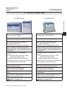
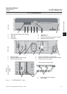
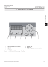
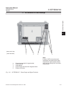
Front panel
The analyzer’s front panel consists of one
4x20-character alphanumeric LC display, a
membrane keyboard and three status LEDs
(Fig. 1-6).
The colors of the LEDs are based on
the NAMUR NE 44 specications. The LEDs
are activated according to the NE 107 stan-
dards and correspond to the following status
messages: “Failure”, “Function check”, “Out of
specication” and “Maintenance request”.
A vacuum uorescent display can be tted
instead of the LCD, making the information
displayed more easily readable in low light-
levels. The display is covered by an impact te-
sted glass to protect it in harsh environments.
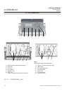
Electrical connections
Electrical connections are provided via inter-
nal tube ttings, the cables being fed through
cable glands at the right side of the unit (Fig.
1-8). The front cover of the housing swings
open to the left once the fasteners have been
released.
Connection to power supply
Mains power is supplied via the screw-type
terminals with integrated fuse holders at the
right of the housing, near the front. The wide
range power supply unit mounted internally
enables the analyzers to be used worldwi-
de.
Interface signals
In the basic conguration, the unit has 36 inter-
nal screw-type terminals for interface signals,
providing one analog output (4[0]-20 mA)
and the contacts for the four (NAMUR) sta-
tus relays. Further analog outputs can also
be provided, e.g. to provide a measurement
signal at different resolutions. A maximum of
four analog outputs is possible.
A serial Modbus interface can also be installed
on request (RS 232 or RS 485 with Modbus
RTU protocol
); alternatively an RJ45 socket
gives access to Ethernet-Modbus-TCP.
Digital inputs and outputs can be used to
control analyzer functions and external
components. The 7 inputs and 9 outputs are
connected to peripheral devices via a further
36-terminal strip. The number of digital inputs
and outputs can be doubled (to 14 inputs and
18 outputs) by adding a second card and an
additional 36-terminal strip.
Detailed technical information on the various
interfaces can be found in
1.3, page1-9
The conguration of the terminals is described
in chapter 4 “Installation” and the software
settings in chapter 6 “Software”.
A further submin-D socket, which is not in
detail described in this manual, is also located
inside the unit, and is designated as a Service
Interface.