


Emerson Process Management GmbH & Co. OHG 4-25
X-STREAM X2
Instruction Manual
HASX2E-IM-HS
02/2012
4
Installation
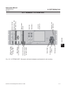
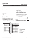
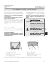
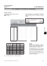
Fig. 4-20: X-STREAM X2XF Field Housings - Arrangement of Terminals, Cable Glands and Gas Fittings
4.6.3 Installation - X-STREAM X2XF Field Housings
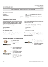
Power and signal cables are connected using
internal screw-type terminals. This requires
opening the unit by releasing the fasteners
on the housing.
Gas connectors are accessible from the un-
derside of the instrument.
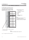
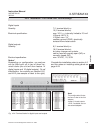
The number and conguration of the gas
inlets and outlets depends on the analytical
application, and is noted on a sticker on the
underside of the instrument next to the con-
nectors.
To simplify installation, we recommend label-
ling the gas lines in accordance with these
markings. This avoids confusion should the
analyzer need to be disconnectedfor main-
tenance.
5 Glands for signal cables
6 Gas inlets and outlets
7 Plugs for openings to connect housings
8 Ethernet connector (optional)
1 Terminals for signal cables
2 Mains lter
3 Power connections with integrated fuses
4 Gland for power cable
6
5
7
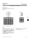
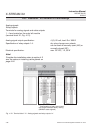
Gas inlets
Gas outlets
18 423
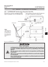
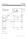
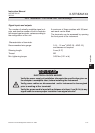
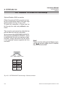
Note on variation XXF!
In case of the dual compartment version XXF, the
electrical connections are established in the upper
compartment, and the gas connections to ttings
at the lower compartment.
Besides this, the design and layout of terminals
and ttings are the same as with the single com-
partment version XLF.
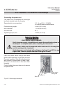
GASKETS AT LOW TEMPERATURES
Consider that enclosure gas-
kets may be frozen when the
instrument is installed outdoors.
Carefully open the enclosure at
temperatures below -10 °C (14 °F)
to not damage the gaskets.
Damaged gaskets void the
ingress protection, possibly
causing property damage,
personal injury or death.