


Emerson Process Management GmbH & Co. OHG 4-37
X-STREAM X2
Instruction Manual
HASX2E-IM-HS
02/2012
4
Installation
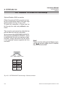
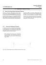
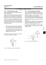
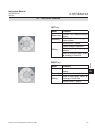
4.7.2 Wiring Inductive Loads
Switching inductive loads creates electroma-
gnetic interference:
When an inductive load (e.g. relay, valve) is
switched off, the magnetic eld resists the
change in current; this induces a high volta-
ge across the coil contacts (several hundred
volts). This impulse propogates through the
connected cables and can influence any
electrical devices nearby or destroy signal
inputs and outputs. This can be avoided with
a simple precaution:
• A silicon diode is connected in parallel to
the load’s contacts. The induced impul-
se is thus short-circuited at its source.
The cathode must be connected to the
positive end of the coil, the anode to the
negative end (Fig. 4-30).
Compatible lter components for standard
valves are available on request.
4.7 Installation - Notes on Wiring
Fig. 4-30: Suppressor diode for inductive loads.
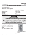
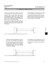
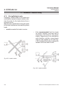
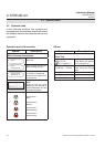
4.7.3 Driving High-current Loads
Loads which draw a current in excess of the
specications for X-STREAM series analyzer
outputs (>30 mA / >1 A) may not be directly
driven from digital or relay outputs.
Such loads require external relays serving as
de-coupling modules: the X-STREAM output
drives the external relay, which in turn drives
the load.
In order to avoid interference, we recommend
supplying the analyzer and the high-current
loads from different sources (Fig. 4-31).
As previously described, the use of sup-
pressor diodes for inductive loads is highly
recommended.
Last
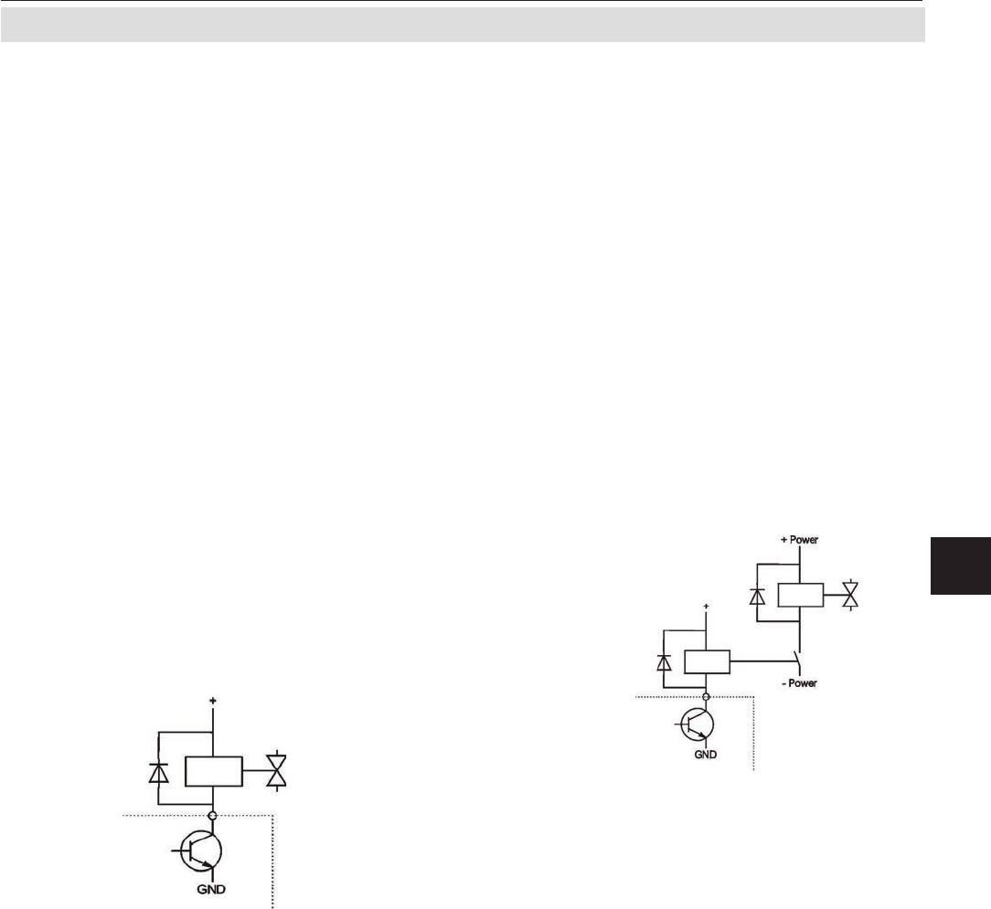
Fig. 4-31: Driving high-current loads
External relay
Analyzer output