


Emerson Process Management GmbH & Co. OHG A-37
A
Appendix
X-STREAM X2
Instruction Manual
HASX2E-IM-EX
02/2012
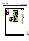
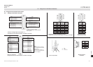
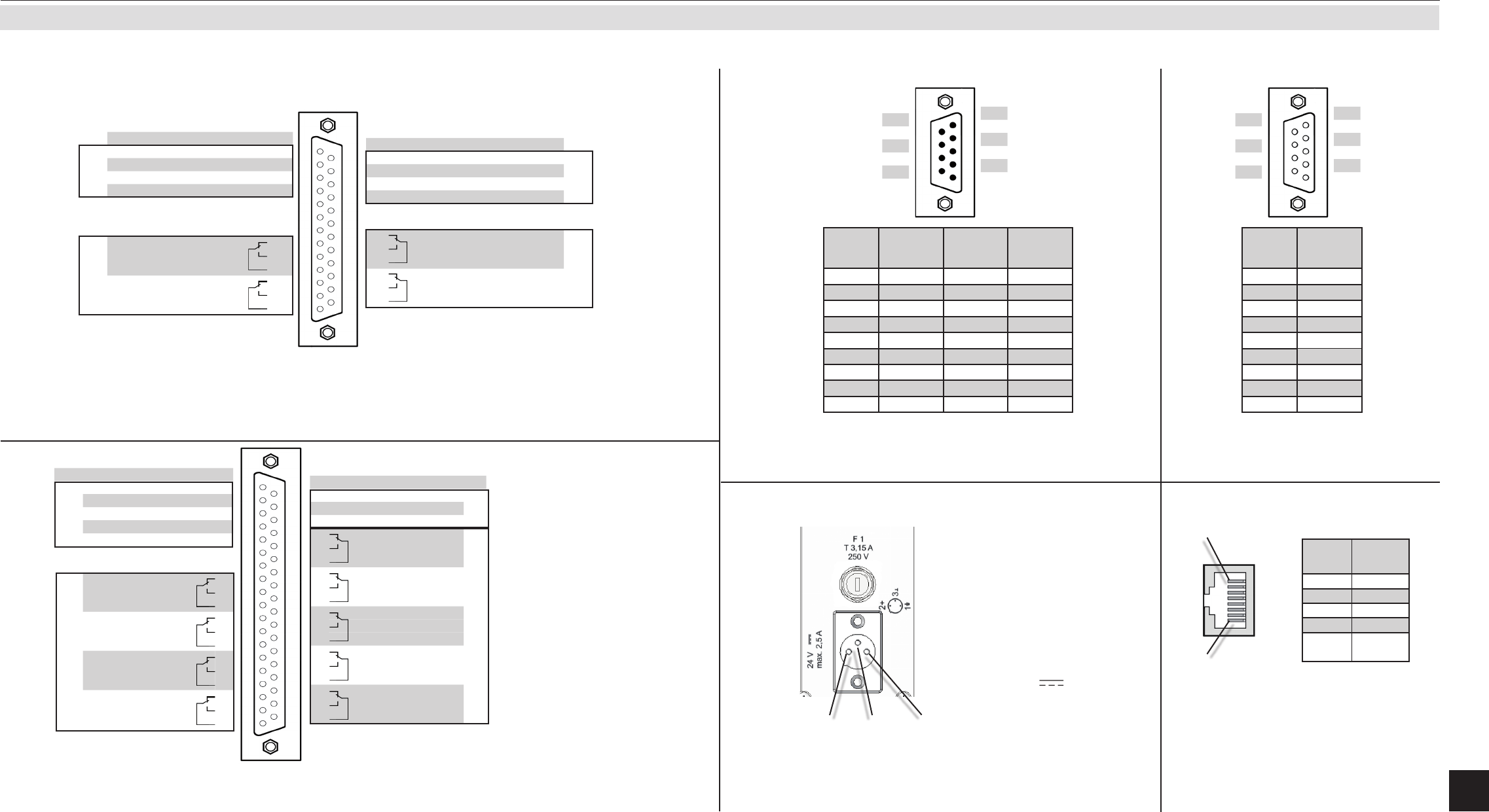
A.7 Assignment of Terminals and Sockets
A
.7.1 Tabletop & Rack Mount Analyzers
A
.7 Assignment Of Terminals And Sockets
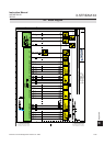
DC 24 V Input (X2GK)
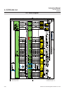
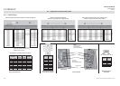
Socket X1 - Analog outputs, relay outputs 1...4
(Assignment of screw terminals adaptor: see XSTA on next page)
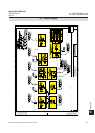
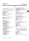
Socket X4 - Digital I/O
(Assignment of screw terminals adaptor: see XSTD on next page)
Pin 1
Pin 8
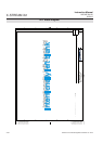
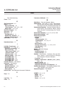
Connector X2 - IOIOI - Serial Modbus interface
(Assignment of screw terminals adaptor: see XSTA on next page)
Service Port Socket -
Serial RS 232 interface
Pin
9
8
7
6
Pin
5
4
3
2
1
Ethernet connector
for Modbus
Note!
Conguration of relay contacts
as per standard factory setting (NAMUR
status signals)
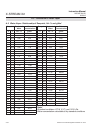
Signal Pin
Analog
outputs
Channel 1, (+) 4 (0) - 20 mA 1
Channel 2, (+) 4 (0) - 20 mA 2
Channel 3, (+) 4 (0) - 20 mA 3
Channel 4, (+) 4 (0) - 20 mA 4
unused 5
unused 6
unused 7
Relay contacts
(Status signals)
Output1 (Failure) NC 8
Output1 (Failure) NO 9
Output1 (Failure) COM 10
Output3 (Off spec) NC 11
Output3 (Off spec) NO 12
Output3 (Off spec) COM 13
Pin Signal
14 Channel 1, GND
Analog
outputs
15 Channel 2, GND
16 Channel 3, GND
17 Channel 4, GND
18 unused
19 unused
20 Output2 (Maintenance request) NC
Relay contacts
(Status signals)
21 Output2 (Maintenance request) NO
22 Output2 (Maintenance request) COM
23 Output4 (Function check) NC
24 Output4 (Function check) NO
25 Output4 (Function check) COM
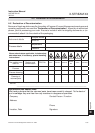
Signal Pin
Input 1 1
Input 2 2
Input 3 3
Input 4 4
GND for all digital inputs 5
unused 6
unused 7
Output 5 NC 8
Output 5 NO 9
Output 5 COM 10
Output 6, NC 11
Output 6, NO 12
Output 6, COM 13
Output 7, NC 14
Output 7, NO 15
Output 7, COM 16
Output 8, NC 17
Output 8, NO 18
Output 8, COM 19
Digital
outputs
Digital
inputs
Pin Signal
20 Input 5
21 Input 6
22 Input 7
23 Output 9, NC
24 Output 9, NO
25 Output 9, COM
26 Output 10, NC
27 Output 10, NO
28 Output 10, COM
29 Output 11, NC
30 Output 11, NO
31 Output 11, COM
32 Output 12, NC
33 Output 12, NO
34 Output 12, COM
35 Output 13, NC
36 Output 13, NO
37 Output 13, COM
Digital
outputs
Digital
inputs
Note!
The conguration illustrated
here is that of the rst socket,
labelled X4.1.
Inputs 8-14 and outputs 14-
22, are on the second socket
(X4.2), if installed.
Pin
6
7
8
9
Pin
1
2
3
4
5
1: ME
2: + 24 V
3: 0 V (⊥)
2 3 1
Pin no.
MOD 485/
2 wire
MOD 485/
4 wire
RS 232
1 Common Common Common
2
not used not used
RXD
3
not used not used
TXD
4
not used
RXD1(+)
not used
5 D1(+) TXD1(+) Common
6
not used not used not used
7
not used not used not used
8
not used
RXD0(-)
not used
9 D0(-) TXD0(-)
not used
Pin no.
RS 232
1 Common
2 RXD
3 TXD
4
not used
5 Common
6
not used
7
not used
8
not used
9
not used
Pin no.
Signal
1 TX+
2 TX-
3 RX+
6 RX-
other
not
used