


Emerson Process Management GmbH & Co. OHG8-38
X-STREAM X2
Instruction Manual
HASX2E-IM-HS
02/2012
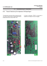
8.4 Troubleshooting on Components
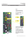
R60
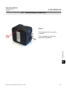
Test connector P4
P4.15
P4.16 +
_
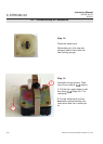
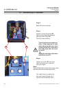
Step 3:
Locate test connector P4 to
measure the bridge voltage:
P4.16 Bridge voltage (+)
P4.15 Bridge voltage (-); GND
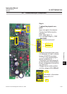
CAUTION!
Do not short-circuit pins!
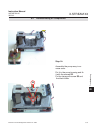
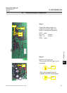
Alternatively the GND signal (-)
is accessible on the main board
BKS, too: Locate X11 (
g.
8-3, page 8-16) .
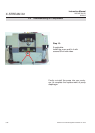
The bridge voltage depends
on range and sample gas and
should be between 3V and 5V.
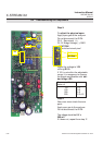
Only if the WAP 100 board has
been replaced, it is necessary to
adjust the voltage with potentio-
meter R60.