


3 - 37
3. SIGNALS AND WIRING
Signal Symbol
Connec-
tor pin
No.
Functions/Applications
I/O
division
Control
mode
P S T
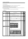
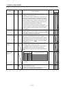
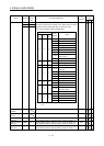
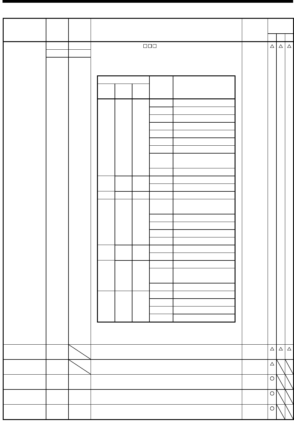
Alarm code ACD 0 CN1-24 To use this signal, set " 1" in parameter No.PD24.
This signal is output when an alarm occurs. When there is no alarm,
respective ordinary signals (RD, INP, SA, ZSP) are output.
Alarm codes and alarm names are listed below.
DO-1
ACD 1 CN1-23
ACD 2 CN1-22
(Note) Alarm code
Alarm
display
Name
CN1-
22
CN1-
23
CN1-
24
0 0 0
88888 Watchdog
AL.12 Memory error 1
AL.13 Clock error
AL.15 Memory error 2
AL.17 Board error
AL.19 Memory error 3
AL.37 Parameter error
AL.8A
Serial communication
time-out error
AL.8E Serial communication error
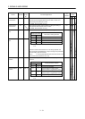
0 0 1
AL.30 Regenerative error
AL.33 Overvoltage
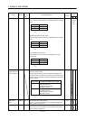
0 1 0 AL.10 Undervoltage
0 1 1
AL.45
Main circuit device
overheat
AL.46 Servo motor overheat
AL.47 Cooling fan alarm
AL.50 Overload 1
AL.51 Overload 2
1 0 0
AL.24 Main circuit error
AL.32 Overcurrent
AL.31 Overspeed
1 0 1 AL.35
Command pulse
frequency alarm
AL.52 Error excessive
1 1 0
AL.16 Encoder error 1
AL.1A Monitor combination error
AL.20 Encoder error 2
AL.25 Absolute position erase
Note. 0: off
1: on
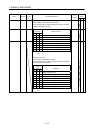
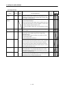
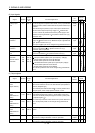
Variable gain
selection
CDPS CDPS is on during gain changing. DO-1
Absolute position
erasing
ABSV ABSV turns on when the absolute position is erased. DO-1
ABS transmission
data bit 0
ABSB0 CN1-22 Outputs ABS transmission data bit 0. CN1-22 acts as ABSB0 only
during ABS transmission data transmission. (Refer to chapter 14.)
DO-1
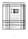
ABS transmission
data bit 1
ABSB1 CN1-23 Outputs ABS transmission data bit 1. CN1-23 acts as ABSB1 only
during ABS transmission data transmission. (Refer to chapter 14.)
DO-1
ABS transmission
data ready
ABST CN1-25 Outputs ABS transmission data ready. CN1-25 acts as ABST only
during ABS transmission data transmission. (Refer to chapter 14.)
DO-1