


5 - 39
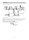
5. PARAMETERS
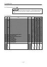
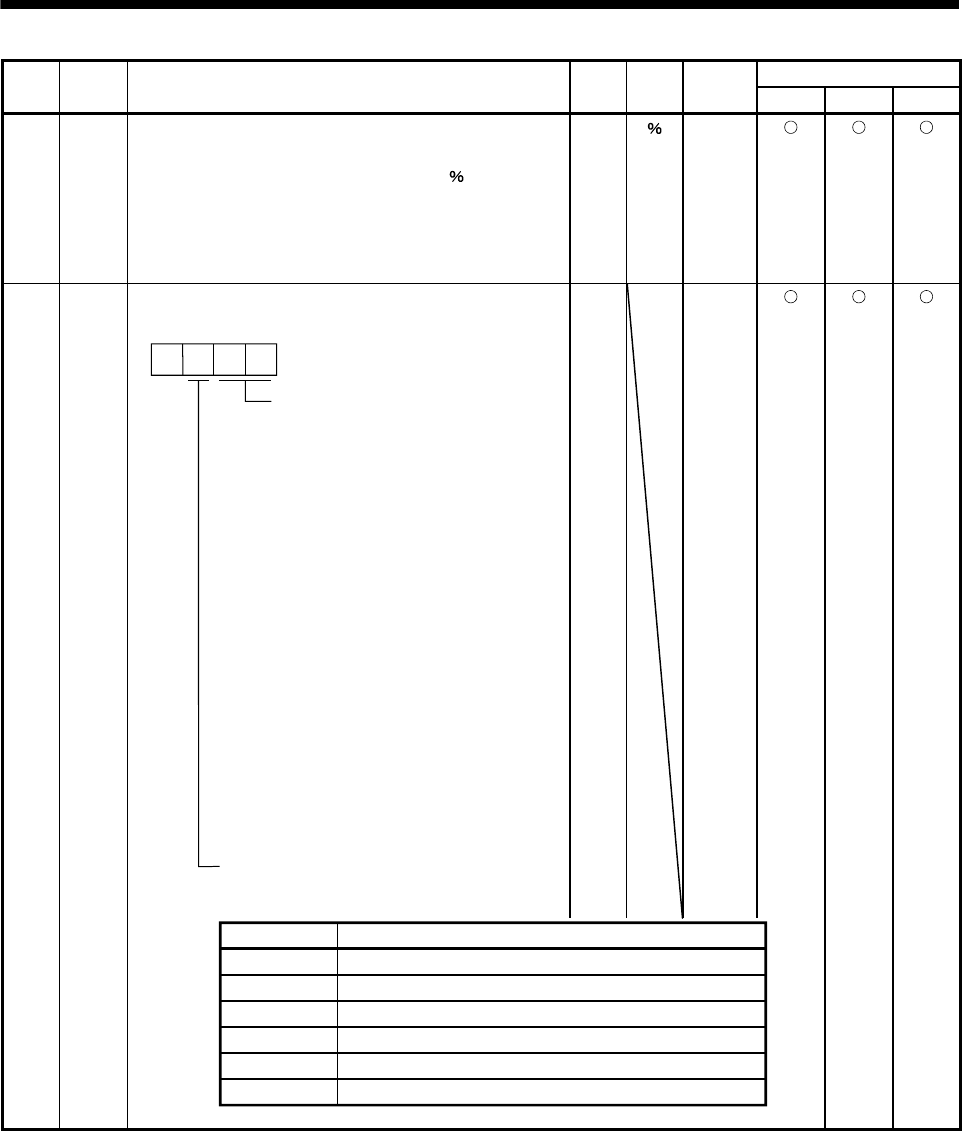
No. Symbol Name and function
Initial
value
Unit
Setting
range
Control mode
Position Speed Torque
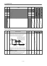
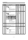
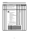
PC35 TL2 Internal torque limit 2
Set this parameter to limit servo motor torque on the
assumption that the maximum torque is 100[
].
When 0 is set, torque is not produced.
When torque is output in analog monitor output, this set
value is the maximum output voltage (8V). (Refer to section
3.6.1 (5)).
100.0
0
to
100.0
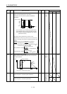
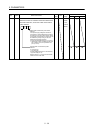
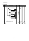
PC36 *DMD Status display selection
Select the status display to be provided at power-on.
0
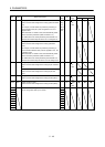
Selection of status display at power-on
0: Cumulative feedback pulse
1: Servo motor speed
2: Droop pulse
3: Cumulative command pulses
4: Command pulse frequency
5: Analog speed command voltage (Note 1)
6: Analog torque command voltage (Note 2
)
7: Regenerative load ratio
8: Effective load ratio
9: Peak load ratio
A: Instantaneous torque
B: Within one-revolution position
(1 pulse unit)
C: Within one-revolution position
(100 pulse unit)
D: ABS counter
E: Load inertia moment ratio
F: Bus voltage
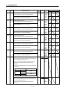
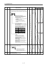
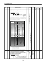
In speed control mode. Analog speed limit
voltage in torque control mode.
In torque control mode. Analog torque limit
voltage in speed or position control mode.
Note 1.
2.
Status display at power-on in corresponding control
mode
0: Depends on the control mode.
0000h Refer to
name
and
function
column.
Position
Position/speed
Speed
Speed/torque
Torque
Torque/position
Status display at power-on
Cumulative feedback pulses
Cumulative feedback pulses/servo motor speed
Servo motor speed
Servo motor speed/analog torque command voltage
Analog torque command voltage
Analog torque command voltage/cumulative feedback pulses
1: Depends on the first digit setting of this parameter.
Control mode