


3 - 32
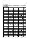
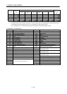
3. SIGNALS AND WIRING
Device Symbol
Connec-
tor pin
No.
Functions/Applications
I/O
division
Control
mode
P S T
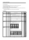
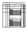
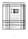
Speed selection 1 SP1 CN1-41 <Speed control mode>
Used to select the command speed for operation.
When using SP3, make it usable by making the setting of parameter
No.PD03 to PD08, PD10 to PD12.
DI-1
Speed selection 2 SP2 CN1-16 (Note)
Input device
Speed command
DI-1
SP3 SP2 SP1
0 0 0 Analog speed command (VC)
0 0 1
Internal speed command 1 (parameter No.PC05)
0 1 0
Internal speed command 2 (parameter No.PC06)
Speed selection 3 SP3 0 1 1
Internal speed command 3 (parameter No.PC07)
DI-1
1 0 0
Internal speed command 4 (parameter No.PC08)
1 0 1
Internal speed command 5 (parameter No.PC09)
1 1 0
Internal speed command 6 (parameter No.PC10)
1 1 1
Internal speed command 7 (parameter No.PC11)
Note. 0: off
1: on
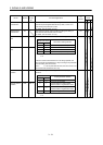
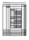
<Torque control mode>
Used to select the limit speed for operation.
When using SP3, make it usable by making the setting of parameter
No.PD03 to PD08, PD10 to PD12.
(Note)
Input device
Speed limit
SP3 SP2 SP1
0 0 0 Analog speed limit (VLA)
0 0 1 Internal speed limit 1 (parameter No.PC05)
0 1 0 Internal speed limit 2 (parameter No.PC06)
0 1 1 Internal speed limit 3 (parameter No.PC07)
1 0 0 Internal speed limit 4 (parameter No.PC08)
1 0 1 Internal speed limit 5 (parameter No.PC09)
1 1 0 Internal speed limit 6 (parameter No.PC10)
1 1 1 Internal speed limit 7 (parameter No.PC11)
Note. 0: off
1: on