


3 - 59
3. SIGNALS AND WIRING
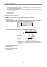
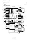
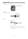
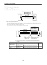
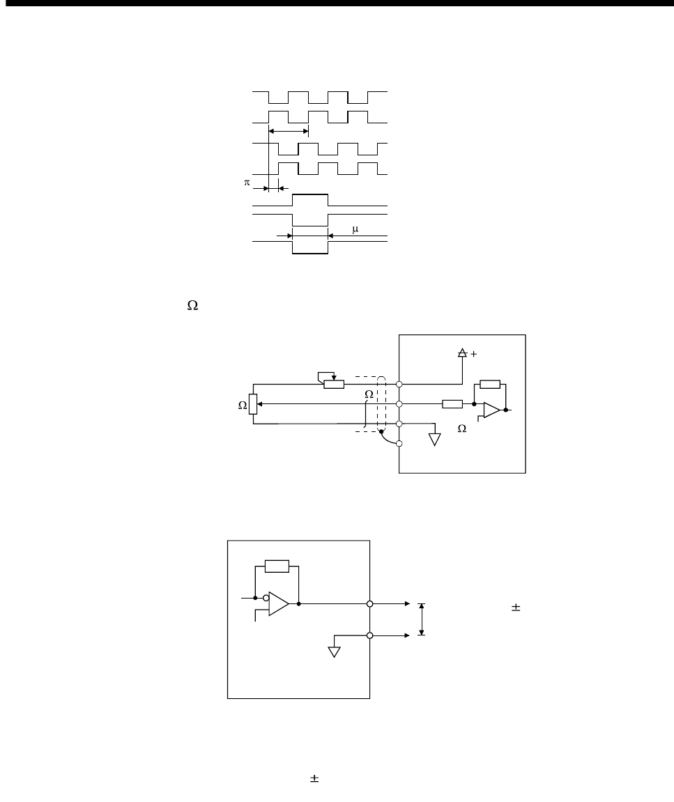
2) Output pulse
Servo motor CCW rotation
LA
LAR
LB
LBR
LZ
LZR
T
/2
OP
Time cycle (T) is determined by the settings
of parameter No.PA15 and PC19.
400 s or longer
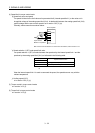
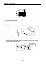
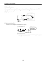
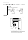
(5) Analog input
Input impedance 10 to 12k
Upper limit setting 2k
15VDC
P15R
VC, etc
LG
SD
2k
Servo amplifier
Approx.
10k
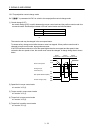
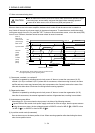
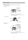
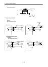
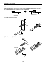
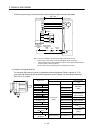
(6) Analog output
LG
MO1
Servo amplifier
(MO2)
Output voltage: 10V (Note)
Max. Output current: 1mA
Resolution: 10 bits or equivalent
Note. Output voltage range varies depending on the monitored signal. (Refer to section
5.3.3.)
When connecting an analog output to an external device, use one whose withstand
voltage is
15VDC or more.