


6
13.5.8 Test operation mode ..................................................................................................................... 13-27
13.5.9 Output signal pin ON/OFF output signal (DO) forced output ....................................................... 13-30
13.5.10 Alarm history ............................................................................................................................... 13-31
13.5.11 Current alarm .............................................................................................................................. 13-32
13.5.12 Other commands ......................................................................................................................... 13-33
14. ABSOLUTE POSITION DETECTION SYSTEM 14- 1 to 14-66
14.1 Outline ................................................................................................................................................... 14- 1
14.1.1 Features ......................................................................................................................................... 14- 1
14.1.2 Restrictions ..................................................................................................................................... 14- 2
14.2 Specifications ........................................................................................................................................ 14- 3
14.3 Battery replacement procedure ............................................................................................................ 14- 4
14.3.1 When replacing battery with the control circuit power ON ............................................................ 14- 4
14.3.2 When replacing battery with the control circuit power OFF .......................................................... 14- 4
14.4 Battery installation procedure ............................................................................................................... 14- 5
14.5 Procedure to replace battery with the control circuit power OFF ........................................................ 14- 5
14.5.1 Preparation for battery replacement .............................................................................................. 14- 5
14.5.2 Replacement procedure ................................................................................................................ 14- 6
14.6 Standard connection diagram ............................................................................................................... 14- 7
14.7 Signal explanation ................................................................................................................................. 14- 8
14.8 Startup procedure ................................................................................................................................. 14- 9
14.9 Absolute position data transfer protocol .............................................................................................. 14-10
14.9.1 Data transfer procedure ................................................................................................................ 14-10
14.9.2 Transfer method ............................................................................................................................ 14-11
14.9.3 Home position setting.................................................................................................................... 14-22
14.9.4 Use of servo motor with an electromagnetic brake ...................................................................... 14-24
14.9.5 How to process the absolute position data at detection of stroke end ........................................ 14-25
14.10 Examples of use ................................................................................................................................ 14-26
14.10.1 MELSEC FX
(2N)-32MT (FX(2N)-1PG) ......................................................................................... 14-26
14.10.2 MELSEC A1SD75 ....................................................................................................................... 14-38
14.10.3 MELSEC QD75 ........................................................................................................................... 14-51
14.11 Absolute position data transfer errors ............................................................................................... 14-59
14.11.1 Corrective actions ....................................................................................................................... 14-59
14.11.2 Error resetting conditions ............................................................................................................ 14-61
14.12 Communication-based ABS transfer system .................................................................................... 14-62
14.12.1 Serial communication command ................................................................................................ 14-62
14.12.2 Absolute position data transfer protocol ..................................................................................... 14-62
14.13 Confirmation of absolute position detection data .............................................................................. 14-66
15. SERVO AMPLIFIERS WITH A LARGE CAPACITY (30k TO 55kW) 15- 1 to 15-102
15.1. Functions and menus .......................................................................................................................... 15- 1
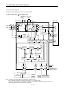
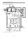
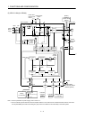
15.1.1 Function block diagram .................................................................................................................. 15- 2
15.1.2 Packing list ..................................................................................................................................... 15- 4
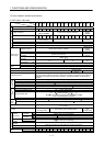
15.1.3 Standard specifications .................................................................................................................. 15- 5
15.1.4 Model definition .............................................................................................................................. 15- 8
15.1.5 Combinations of converter units, drive unit and servo motors ..................................................... 15- 9
15.1.6 Parts identification ......................................................................................................................... 15-10