


3 - 48
3. SIGNALS AND WIRING
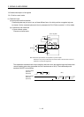
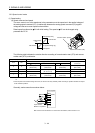
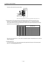
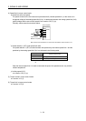
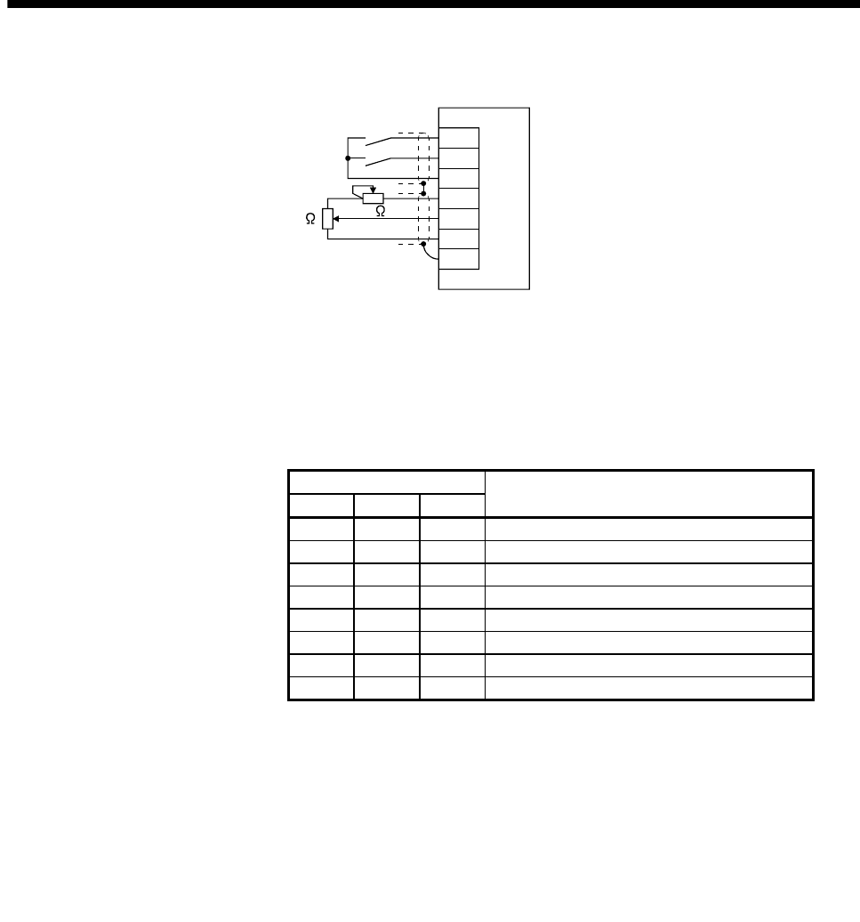
Generally, make connection as shown below.
SP2
DOCOM
P15R
VLA
LG
SD
SP1
Japan resistor
RRS10 or equivalent
(Note)
2k
2k
Servo amplifier
Note. For the sink I/O interface. For the source I/O interface, refer to section 3.8.3.
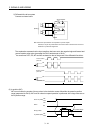
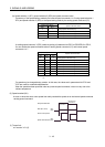
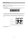
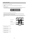
(b) Speed selection 1(SP1)/speed selection 2(SP2)/speed selection 3(SP3) and speed limit values
Choose any of the speed settings made by the internal speed limits 1 to 7 using speed selection
1(SP1), speed selection 2(SP2) and speed selection 3(SP3) or the speed setting made by the analog
speed limit (VLA), as indicated below.
(Note) Input device
Speed limit value
SP3 SP2 SP1
0 0 0 Analog speed limit (VLA)
0 0 1 Internal speed limit 1 (parameter No.PC05)
0 1 0 Internal speed limit 2 (parameter No.PC06)
0 1 1 Internal speed limit 3 (parameter No.PC07)
1 0 0 Internal speed limit 4 (parameter No.PC08)
1 0 1 Internal speed limit 5 (parameter No.PC09)
1 1 0 Internal speed limit 6 (parameter No.PC10)
1 1 1 Internal speed limit 7 (parameter No.PC11)
Note. 0: off
1: on
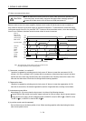
When the internal speed limits 1 to 7 are used to command the speed, the speed does not vary with the
ambient temperature.
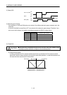
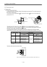
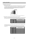
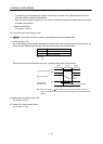
(c) Limiting speed (VLC)
VLC turns on when the servo motor speed reaches the speed limited using any of the internal speed
limits 1 to 7 or the analog speed limit (VLA).