


13 - 2
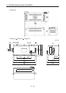
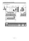
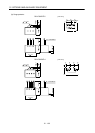
13. COMMUNICATION FUNCTION
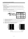
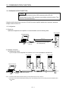
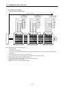
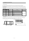
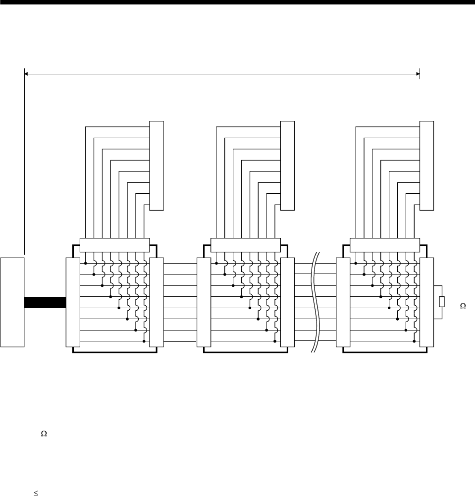
(b) Cable connection diagram
Wire the cables as shown below.
7
1
2
3
4
5
6
8
7
1
2
3
4
5
6
8
12345678
7
1
2
3
4
5
6
8
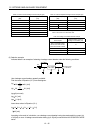
(Note 4, 5)
(Note 1)
Axis 1 servo amplifier
CN3 connector
(RJ45 connector)
LG
P5D
RDP
SDN
SDP
RDN
LG
NC
(Note 5)
(Note 5)
7
1
2
3
4
5
6
8
7
1
2
3
4
5
6
8
12345678
7
1
2
3
4
5
6
8
LG
P5D
RDP
SDN
SDP
RDN
LG
NC
(Note 4, 5)
(Note 1)
Axis 2 servo amplifier
CN3 connector
(RJ45 connector)
7
1
2
3
4
5
6
8
7
1
2
3
4
5
6
8
12345678
7
1
2
3
4
5
6
8
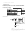
LG
P5D
RDP
SDN
SDP
RDN
LG
NC
(Note 4, 5)
(Note 2)
(Note 1, 7)
Axis n servo amplifier
CN3 connector
(RJ45 connector)
(Note 6) Branch connector (Note 6) Branch connector (Note 6) Branch connector
(Note 3) 30m or less
RDN
150
RDP
(Note 8)
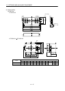
Note 1. Recommended connector (Hirose Electric)
Plug: TM10P-88P
Connection tool: CL250-0228-1
2. The final axis must be terminated between RDP (pin No.3) and RDN (pin No.6) on the receiving side (servo amplifier) with a
150
resistor.
3. The overall length is 30m or less in low-noise environment.
4. The wiring between the branch connector and servo amplifier should be as short as possible.
5. Use the EIA568-compliant cable (10BASE-T cable, etc.).
6. Recommended branch connector: BMJ-8 (Hakko Electric Machine Works)
7. n
32 (Up to 32 axes can be connected.)
8. RS-422/232C conversion cable DSV-CABV (Diatrend)