


10 - 2
10. OUTLINE DRAWINGS
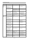
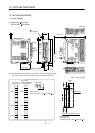
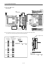
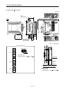
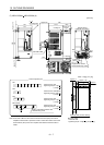
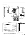
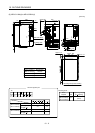
(2) MR-J3-40A
MR-J3-60A
MR-J3-40A1
[Unit: mm]
170
6
Approx.14
Approx.
25.5
5
Approx.68
With MR-J3BAT
CN5CN6CN3CN1CN2CN2LCN4
L1L2 L3N P1 P2 P C D L11 L21 U V W
CHARGE
CNP1
L1
L2
L3
N
P1
P2
P
C
D
L11
L21
U
V
W
CNP2
CNP3
156
6
6
161
168
6
6
mounting hole
Approx.80
(Note)
(Note)
Note. This data applies to the 3-phase or 1-phase 200 to 230VAC and 1-phase 230VAC power supply models.
For 1-phase, 100 to 120VAC power supply, refer to the terminal signal layout.
Mass: 1.0 [kg] (2.21 [lb])
L1
L
2
L3
N
P
1
P
2
P
C
D
L
11
L
21
U
V
W
CNP3
CNP2
CNP1
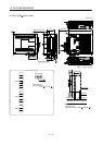
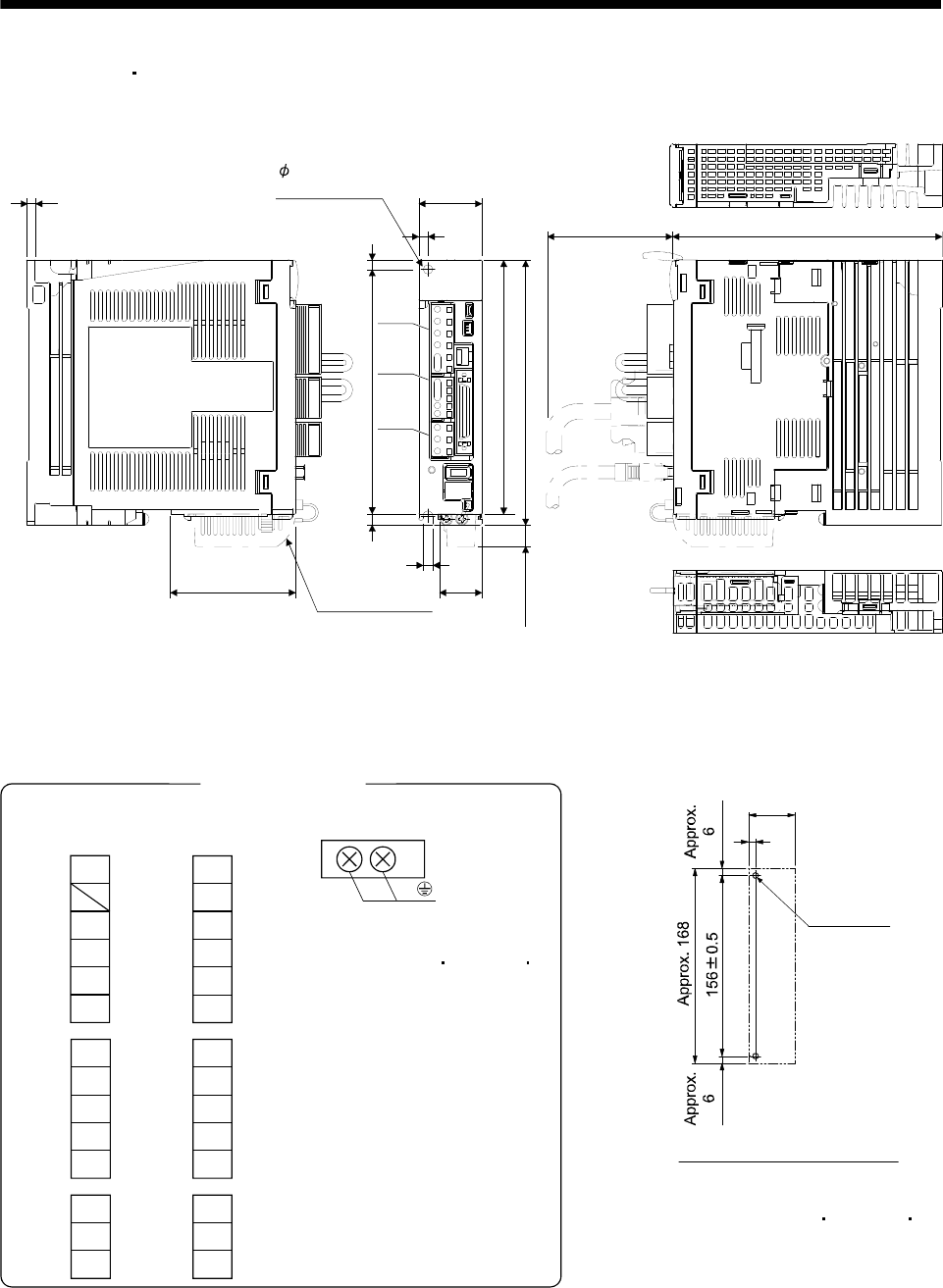
PE terminal
Screw size: M4
Tightening torque: 1.2 [N m] (10.6 [lb in])
Terminal signal layout
P
C
D
L
11
L
21
U
V
W
CNP3
CNP2
For 3-phase
200 to 230VAC and
1-phase 230VAC
L
1
L
2
N
P
1
P
2
CNP1
For 1-phase
100 to 120VAC
Mounting screw
Screw size: M5
Tightening torque: 3.24[N m] (28.7[lb in])
Mounting hole process drawing
2-M5 screw
6
Approx.
40