


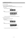
14 - 7
14. ABSOLUTE POSITION DETECTION SYSTEM
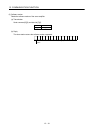
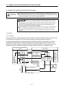
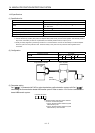
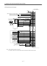
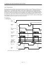
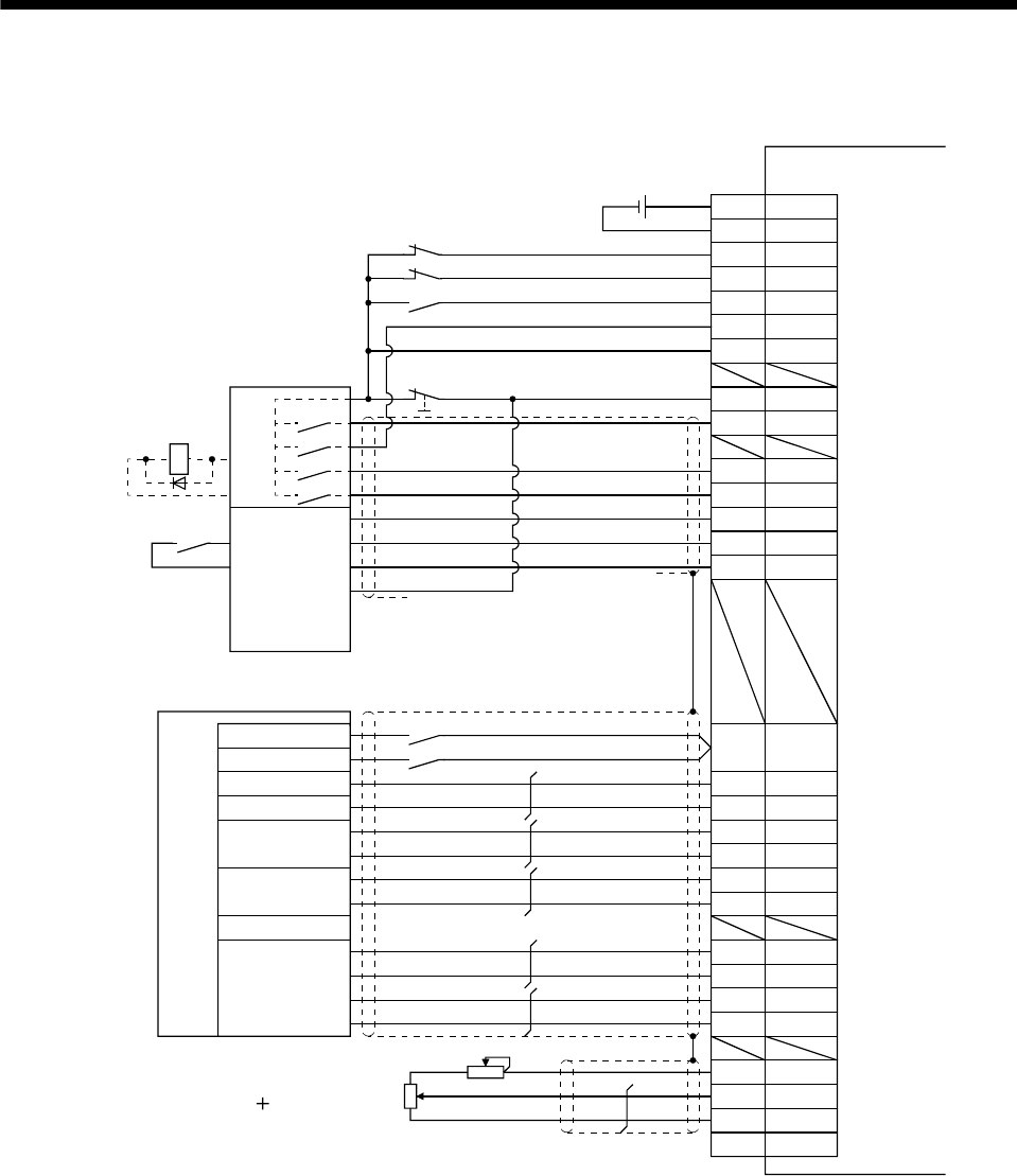
14.6 Standard connection diagram
Analog torque limit
10V/max.torque
Proximity dog signal
Stop signal
Power supply (24V)
Ready
Zero-point
signal
Clear
Command
pulses
(for differential
line driver type)
Reset
CR
DOCOM
20
46
DOCOM
43LSP
44LSN
18TL
19RES
46
DOCOM
15SON
42EMG
17ABSM
18ABSR
22
ABSB0
23
ABSB1
25ABST
DICOM
DOCOM
47
21
DICOM
49RD
1P15R
33OP
41
47
10PP
11PG
35NP
36NG
1P15R
27TLA
28LG
Plate SD
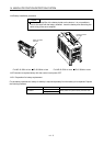
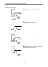
Servo amplifier
I/O unit
Dog
Stop
Input
Out
put
Electromagnetic
brake output
Reset
EMG (Note 1)
(Note 2)
Emergency stop
Servo-on
ABS transmission
mode
ABS request
ABS transmission data bit 0
ABS transmission data bit 1
ABS transmission data ready
Upper limit setting
CN1
RA2
24VDC
External torque limit selection
Stroke end in reverse rotation
Stroke end in forward rotation
Positioning module
Note 1. Always install the emergency stop switch.
2. For operation, always turn on forward rotation stroke end (LSP)/reverse rotation stroke end (LSN).