


15 - 94
15. SERVO AMPLIFIERS WITH A LARGE CAPACITY
(
30k TO 55kW
)
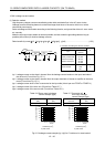
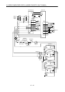
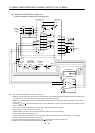
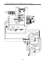
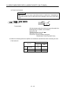
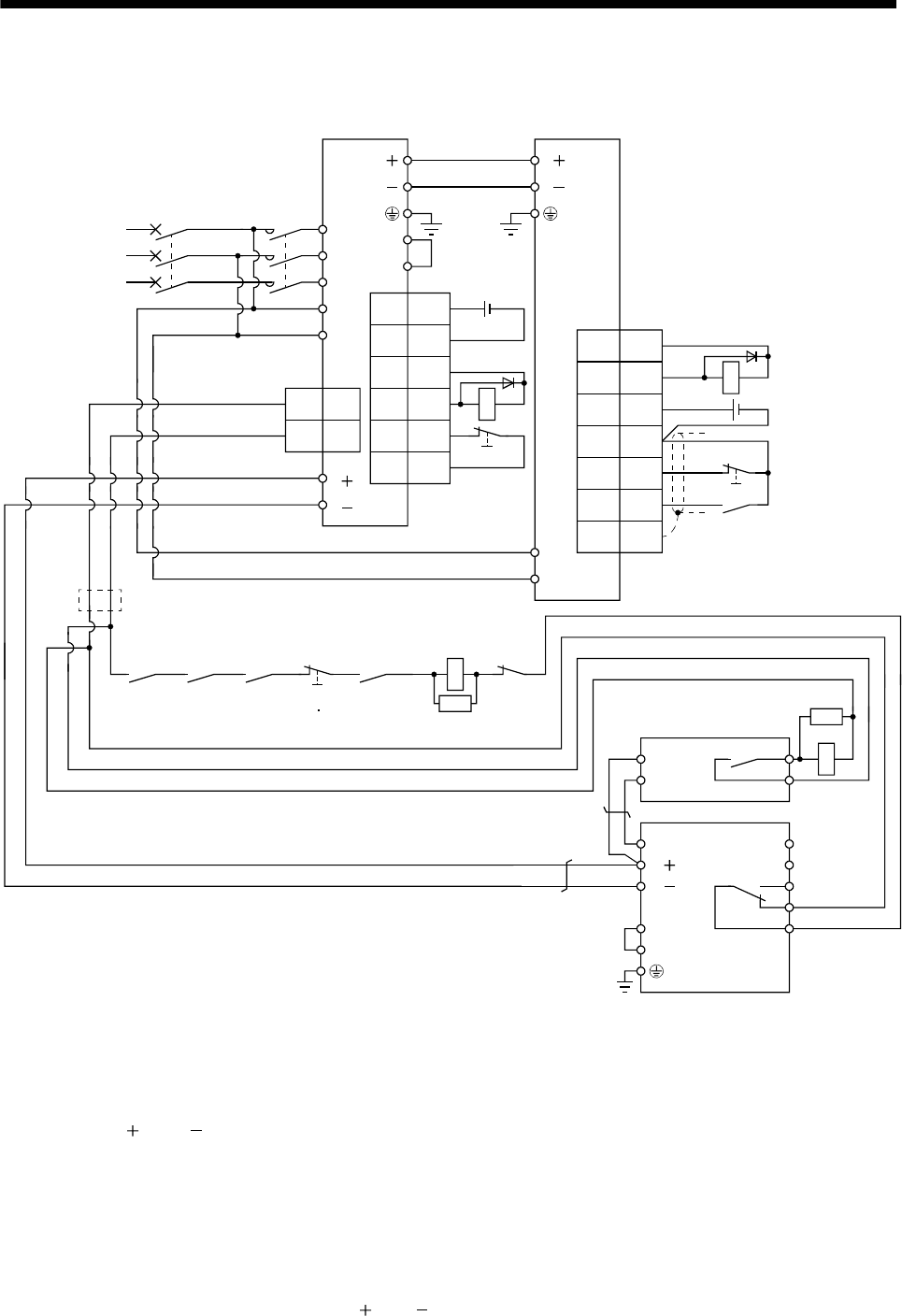
(b) Combination with MT-BR5-(H) resistor unit
1) When connecting a brake unit to a converter unit
RA3RA1 RA2
OFF/ON
Converter
unit trouble
Operation
ready
Drive unit
trouble
Emergency stop
(EMG EM1)
(Note 2)
(Note 8)
Servo motor
thermal relay
MC
RA5
SK
Drive unitConverter unit
L
1
L
2
L
3
L11
L
21
(Note 1)
Power
supply
L
L
L
L
1MC1
2MC2
CNP1
L11
L
21
(Note 5)
CN1
1
DICOM
5
DOCOM
6
DICOM
2ALM
7EM1
9
DOCOM
N/
P/
BUE
SD
PR
B
C
A
SD
MSG
(Note 4)
(Note 7)
FR-BU2-(H)
MT-BR5-(H)
P
PR
(Note 6)
(Note 10)
P
1
P2
L
L
(Note 9)
(Note 3)
CN1
(Note 2)
21
DICOM
48 ALM
20
DICOM
46
DOCOM
42 EMG
15 SON
Plate SD
RA1
24VDC
24VDC
RA5
TH2
TH1
MCNFB
(Note 2)
RA2
SK
Note 1. For power supply specifications, refer to section 15.1.3.
2. Make up a sequence that will concurrently turn off the Emergency stop (EMG) of the drive unit and the Forced stop (EM1) of the
converter unit, and shut off the main circuit power supply by the external sequence.
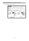
3. Make sure to connect between P
1 and P2 terminals (Factory-wired). When using the power factor improving DC reactor, refer to
section 15.9.6.
4. Connect P/
and N/ terminals of the brake unit to a correct destination. Incorrect connection results in the converter unit and
brake unit malfunction.
5. For the converter unit and the drive unit of 400V class, a stepdown transformer is required.
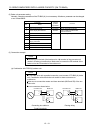
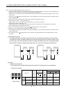
6. Contact rating: 1a contact, 110VAC_5A/220VAC_3A
Normal condition: TH1-TH2 is not conducting. Abnormal condition: TH1-TH2 is conducting.
7. Contact rating: 230VAC_0.3A/30VDC_0.3A
Normal condition: B-C is conducting/A-C is not conducting. Abnormal condition: B-C is not conducting/A-C is conducting.
8. Connect the thermal relay censor of the servo motor.
9. Do not connect more than one cable to each L
and L terminals of TE2-1 of the converter unit.
10. Make sure to connect between BUE and SD terminals (Factory-wired).