


12 - 23
12. OPTIONS AND AUXILIARY EQUIPMENT
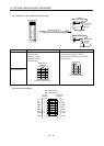
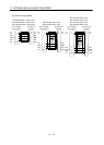
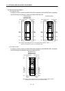
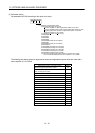
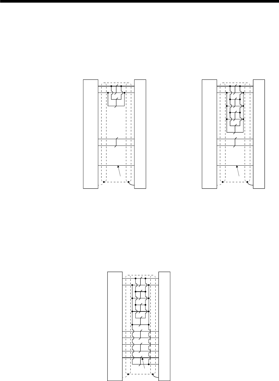
(b) Cable internal wiring diagram
1) For less than 30m
To fabricate, use the connector set MR-ECNS (IP20 compatible) or MR-ENECNS (IP67 compatible).
Use the following wiring diagram to fabricate a cable shorter than 30m.
MR-ENECBL20M-H
(Note)
Servo amplifier side
P5
LG
1
2
MR
MRR
3
4
F
S
9
SD
C
D
R
N
LG
MR
MRR
SHD
P5
P5
LG
1
2
MR
MRR
3
4
F
S
Encoder side
9
SD Plate
C
D
R
N
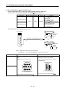
MR-ENECBL2M-H
MR-ENECBL5M-H
MR-ENECBL10M-H
LG
MR
MRR
SHD
P5
BAT BAT BAT BAT
Plate
Servo amplifier side Encoder side
(Note)
Note. Always make connection for use in an absolute position detection system.
Wiring is not necessary for use in an incremental system.
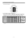
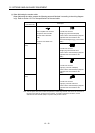
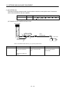
2) For 30m or more
To fabricate, use the connector set MR-ECNS (IP20 compatible) or MR-ENECNS (IP67 compatible).
Use the following wiring diagram to fabricate a cable up to 50m.
(Note)
SD Plate N SHD
P5
LG
1
2
MR
MRR
3
4
MDR 8 B
F
S
A
MD 7
9
C
D
R
LG
MR
MRR
MDR
MD
P5
MCONT
BAT BAT
Servo amplifier side Encoder side
MR-ENECBL30M-H
MR-ENECBL40M-H
MR-ENECBL50M-H
Note. Always make connection for use in an absolute position detection system.
Wiring is not necessary for use in an incremental system.