


3 - 33
3. SIGNALS AND WIRING
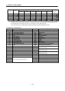
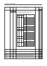
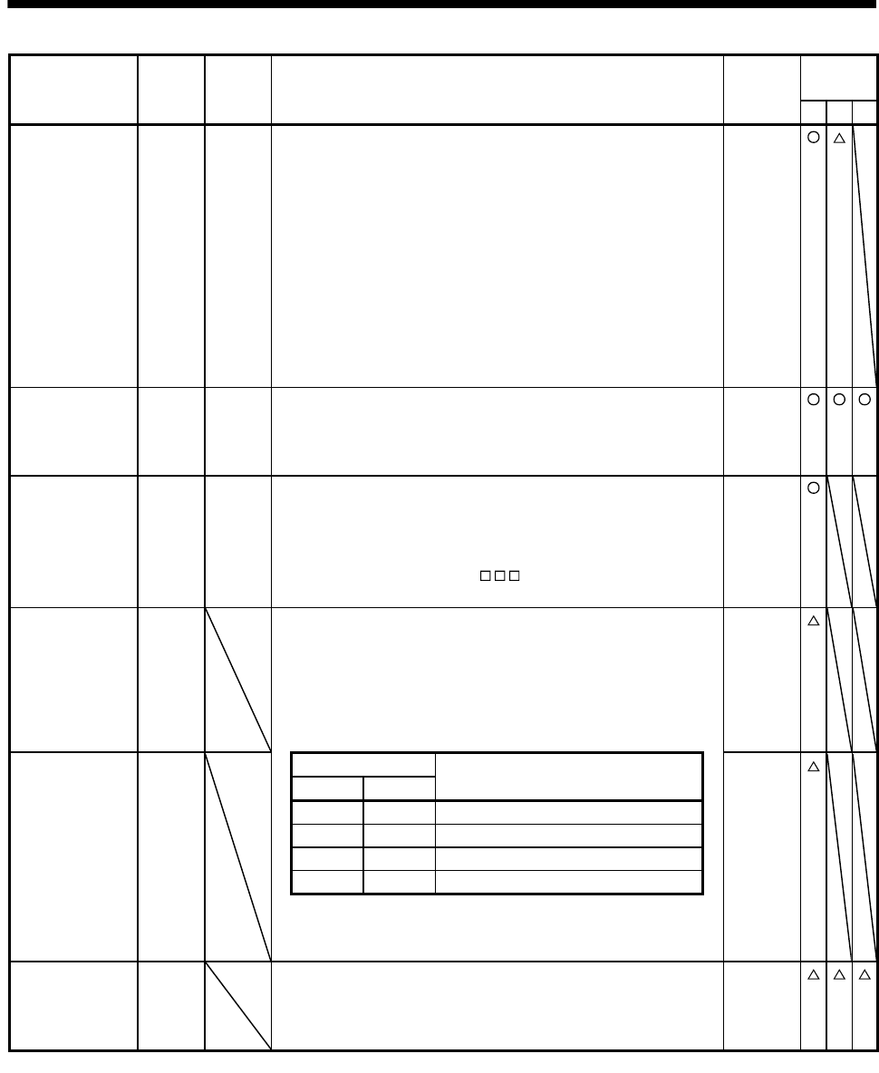
Device Symbol
Connec-
tor pin
No.
Functions/Applications
I/O
division
Control
mode
P S T
Proportion control PC CN1-17 Turn PC on to switch the speed amplifier from the proportional
integral type to the proportional type.
If the servo motor at a stop is rotated even one pulse due to any
external factor, it generates torque to compensate for a position
shift. When the servo motor shaft is to be locked mechanically after
positioning completion (stop), switching on the proportion control
(PC) upon positioning completion will suppress the unnecessary
torque generated to compensate for a position shift.
When the shaft is to be locked for a long time, switch on the
proportion control (PC) and external torque limit selection (TL) at the
same time to make the torque less than the rated by the analog
torque limit (TLA).
DI-1
Emergency stop EMG CN1-42 Turn EMG off (open between commons) to bring the motor to an
emergency stop state, in which the base circuit is shut off and the
dynamic brake is operated. Turn EMG on (short between commons)
in the emergency stop state to reset that state.
DI-1
Clear CR CN1-41 Turn CR on to clear the position control counter droop pulses on its
leading edge. The pulse width should be 10ms or longer.
The delay amount set in parameter No.PB03 (position command
acceleration/deceleration time constant) is also cleared. When the
parameter No.PD22 setting is "
1 ", the pulses are always
cleared while CR is on.
DI-1
Electronic gear
selection 1
CM1 When using CM1 and CM2, make them usable by the setting of
parameters No.PD03 to PD08, PD10 to PD12.
The combination of CM1 and CM2 gives you a choice of four
different electronic gear numerators set in the parameters.
CM1 and CM2 cannot be used in the absolute position detection
system.
DI-1
Electronic gear
selection 2
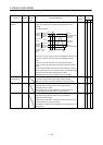
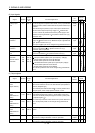
CM2 (Note) Input device
Electronic gear molecule
DI-1
CM2 CM1
0 0 Parameter No.PA06
0 1 Parameter No.PC32
1 0 Parameter No.PC33
1 1 Parameter No.PC34
Note. 0: off
1: on
Gain changing CDP When using this signal, make it usable by the setting of parameter
No.PD03 to PD08, PD10 to PD12.
Turn CDP on to change the load inertia moment ratio and gain
values into the parameter No.PB29 to PB34 values.
DI-1