


3 - 67
3. SIGNALS AND WIRING
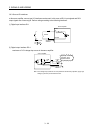
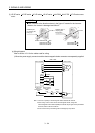
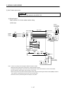
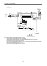
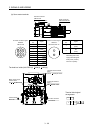
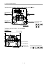
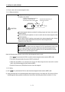
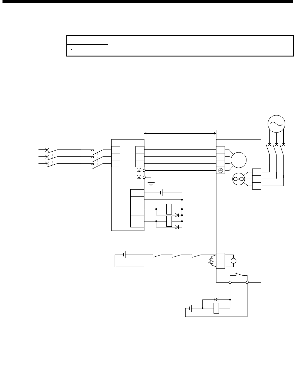
(3) HA-LP series servo motor
POINT
Refer to (2) in this section for HA-LP502, 702.
(a) Wiring diagrams
Refer to section 12.11 for the cables used for wiring.
1) 200V class
NFB
MC
24VDC
ALM
DOCOM
DICOM
MBR
CN1
Servo motorServo amplifier
M
U
V
W
U
V
W
L1
L2
L3
Cooling fan
BU
BV
BW
(Note 2)
50m or less
RA1
RA2
(Note 1)
B1
B2
B
OHS2OHS1
Servo motor
thermal relay
RA3
24VDC
(Note 3)
3-phase
200 to
230VAC
24VDC power
supply for
electromagnetic
brake
RA1
Electromagnetic
brake interlock
(MBR)
RA2
(Note 6)
RA3
Trouble
(ALM)
(Note 5)
NF
(Note 4)
Power supply
of cooling fan
Note 1. There is no polarity in electromagnetic brake terminals B1 and B2.
2. When the power supply for the cooling fan is 1-phase, BW does not exist.
3. Configure the power supply circuit which turns off the magnetic contactor after detection of servo motor thermal.
4. For the cooling fan power supply, refer to section 3.10.2 (3) (b).
5. When using a servo motor with an electromagnetic brake, assign the electromagnetic brake interlock (MBR) to external
output signal in the parameters No.PA04, PD13 to PD16 and PD18.
6. Shut off the circuit by interlocking with the emergency stop switch.