4 - 8
4. STARTUP
No. Start-up sequence Fault Investigation Possible cause Reference
4 Gain adjustment Rotation ripples
(speed fluctuations)
are large at low
speed.
Make gain adjustment in the
following procedure.
1. Increase the auto tuning
response level.
2. Repeat acceleration and
deceleration several times to
complete auto tuning.
Gain adjustment fault Chapter 7
Large load inertia
moment causes the
servo motor shaft to
oscillate side to
side.
If the servo motor may be run with
safety, repeat acceleration and
deceleration several times to
complete auto tuning.
Gain adjustment fault Chapter 7
5 Cyclic operation Position shift occurs Confirm the cumulative command
pulses, cumulative feedback
pulses and actual servo motor
position.
Pulse counting error, etc.
due to noise.
(2) in this
section
(2) How to find the cause of position shift
Servo amplifier
Servo-on (SON),
stroke end
(LSP/LSN) input
Encoder
Q
P
CMX
CDV
C
M
L
Electronic gear
(parameter No.PA06, PA07)
(b) Cumulative command pulses
(c) Cumulative feedback pulses
(d)
(B)
(a)
(A)
(C)
Positioning unit
Servo motor
Machine
Output
pulse
counter
Machine stop
position M
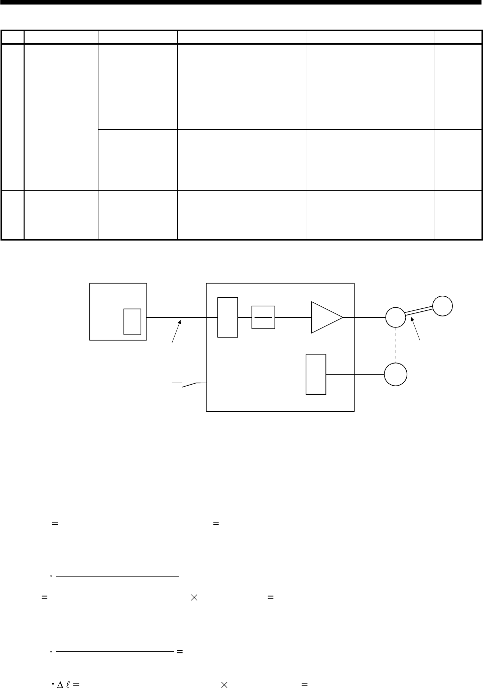
When a position shift occurs, check (a) output pulse counter, (b) cumulative command pulse display, (c)
cumulative feedback pulse display, and (d) machine stop position in the above diagram.
(A), (B) and (C) indicate position shift causes. For example, (A) indicates that noise entered the wiring
between positioning unit and servo amplifier, causing pulses to be miss-counted.
In a normal status without position shift, there are the following relationships.
1) Q
P (positioning unit's output counter servo amplifier's cumulative command pulses)
2) When using the electronic gear
P
CMX (parameter No.PA06)
CDV (parameter No.PA07)
C (cumulative command pulses electronic gear cumulative feedback pulses)
3) When using parameter No.PA05 to set the number of pulses per servo motor one rotation.
FBP (parameter No.PA05)
262144
P C
4) C
M (cumulative feedback pulses travel per pulse machine position)


