


3 - 11
3. SIGNALS AND WIRING
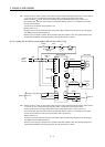
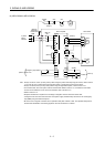
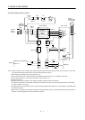
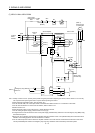
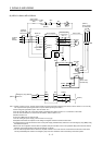
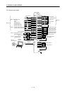
Note 1. To prevent an electric shock, always connect the protective earth (PE) terminal (terminal marked ) of the servo amplifier to
the protective earth (PE) of the control box.
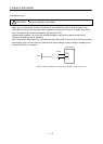
2. Connect the diode in the correct direction. If it is connected reversely, the servo amplifier will be faulty and will not output
signals, disabling the emergency stop (EMG) and other protective circuits.
3. The emergency stop switch (normally closed contact) must be installed.
4. Supply 24VDC 10 300mA current for interfaces from the outside. 300mA is the value applicable when all I/O signals are
used. The current capacity can be decreased by reducing the number of I/O points. Refer to section 3.8.2 (1) that gives the
current value necessary for the interface.
5. When starting operation, always turn on emergency stop (EMG) and Forward/Reverse rotation stroke end (LSP/LSN).
(Normally closed contacts)
6. Trouble (ALM) turns on in normal alarm-free condition. When this signal is switched off (at occurrence of an alarm), the output
of the programmable controller should be stopped by the sequence program.
7. The pins with the same signal name are connected in the servo amplifier.
8. This length applies to the command pulse train input in the differential line driver system. It is 2m or less in the open collector
system.
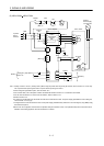
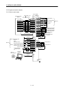
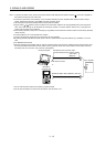
9. Use MRZJW3-SETUP 221E.
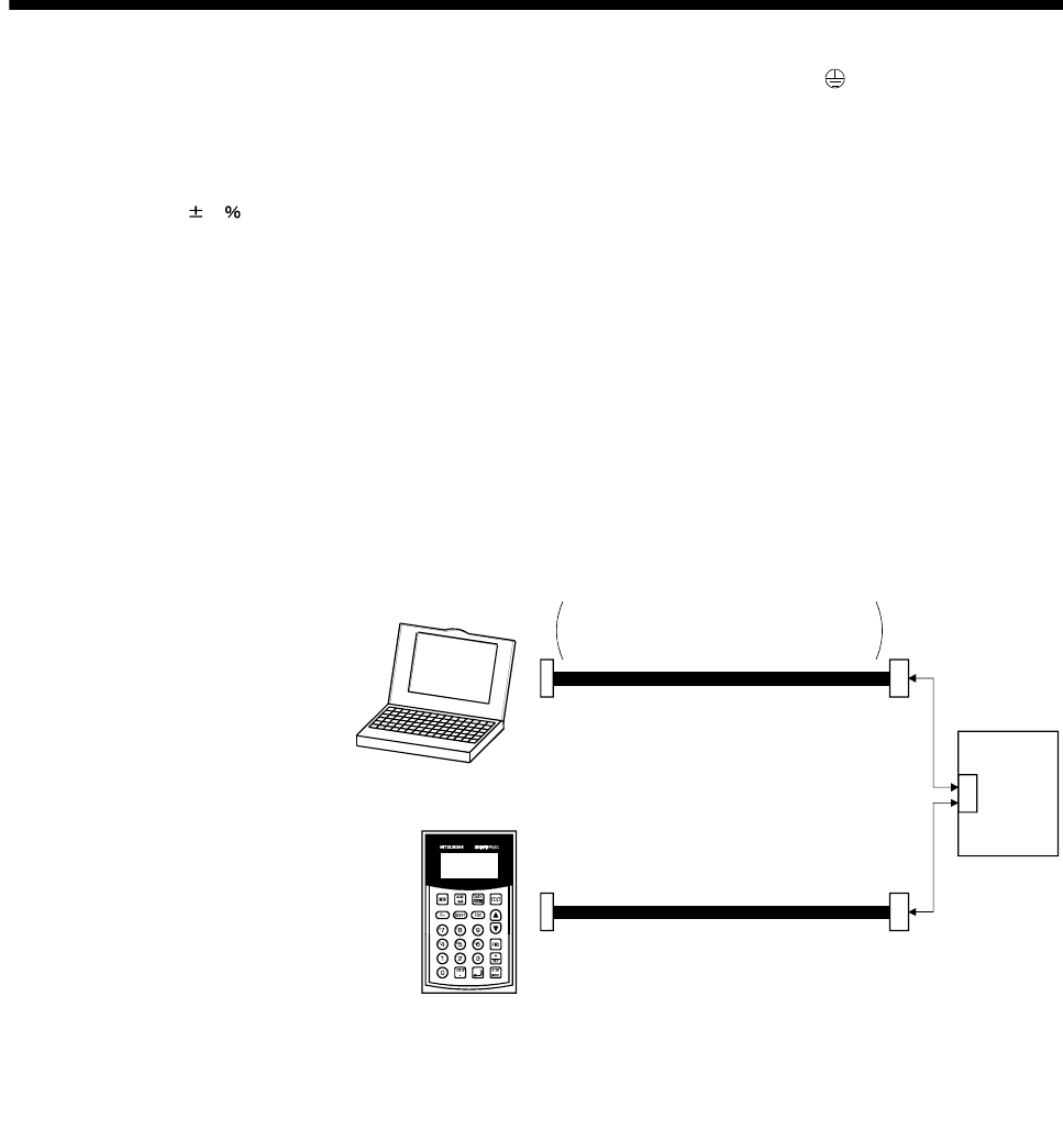
10. Personal computers or parameter units can also be connected via the CN3 connector, enabling RS-422 communication. Note
that using the USB communication function (CN5 connector) prevents the RS-422 communication function (CN3 connector)
from being used, and vice versa. They cannot be used together.
MR-PRU03
parameter unit
CN3
EIA568-compliant cable (10BASE-T cable, etc.)
RS-232C/RS-422 conversion cable
Recommended product: Interface cable
DSV-CABV
(Diatrend)
Personal compute
r
Servo amplifier
or
To RS-232C connector
11. This connection is not required for the QD75D. Depending on the used positioning module, however, it is recommended to
connect the LG and control common terminals of the servo amplifier to enhance noise immunity.
12. For the sink I/O interface. For the source I/O interface, refer to section 3.8.3.