15 - 3
15. SERVO AMPLIFIERS WITH A LARGE CAPACITY
(
30k TO 55kW
)
Servo motor
thermal
Termination
connector
MR-J3-TM
(Option)
CN40
Drive unit
Over
current
Control
power
supply
Current
detector
(Note 1)
Power
supply
L
L
L
L
CN40ACN40B
Optional battery
(For absolute position
detection system)
CN4
MR-J3BAT
CN5 CN3 CN6
Analog monitor
(2 channels)
USB RS-422 D/AA/D
USB RS-422
Controller
Personal
computer
Analog
(2 channels)
D I/O control
Servo on
Command pulse train
input
Start
Failure, etc.
CN1
Cooling fan
Cooling fan
NFB
Pulse input
U
V
W
U
V
W
External dynamic
brake (option)
(Note 2)
Servo motor
M
L
11
L
21
L
11
L
21
Base amplifier
Current
detection
Virtual
encoder
BU
BV
BW
Encoder
OHS2OHS1
CN2
Virtual
motor
Model speed
control
Model
position
Actual position
control
Actual speed
control
Current
control
Model position Model speed Model torque
I/F
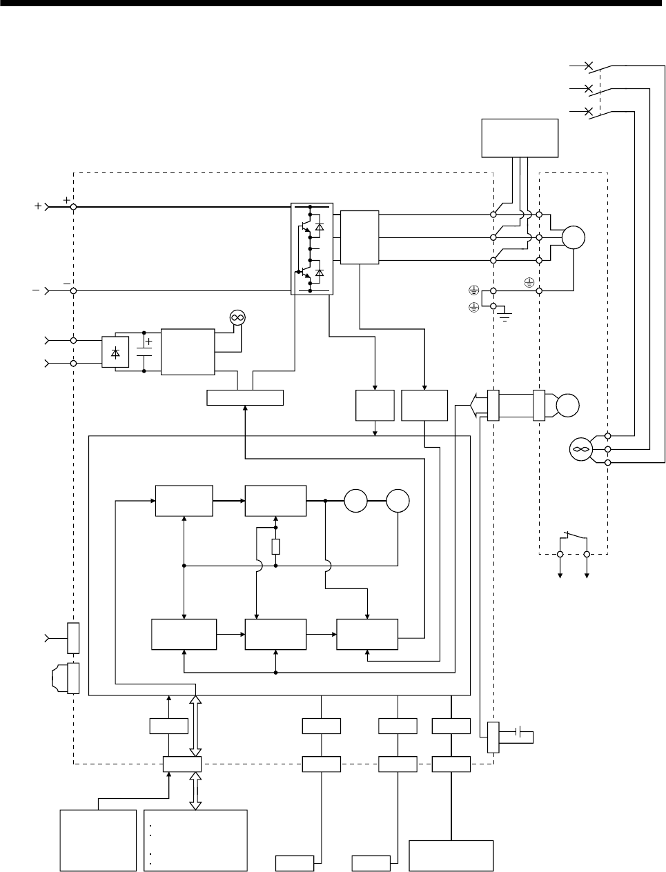
Note 1. Refer to section 15.3.6 for the power supply specification of the servo motor cooling fan.
2. Use an external dynamic brake for the drive unit. Failure to do so will cause an accident because the servo motor does not stop
immediately but coasts at an emergency stop and such conditions. Ensure the safety in the entire system.


