


App. - 1
A
PPENDIX
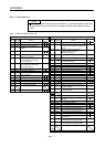
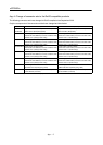
App. 1 Parameter list
POINT
For any parameter whose symbol is preceded by *, set the parameter value and
switch power off once, then switch it on again to make that parameter setting
valid.
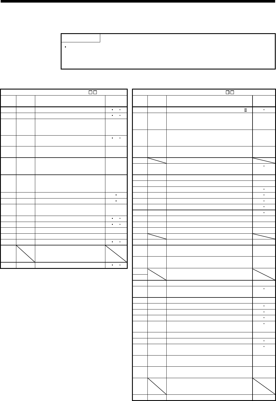
App. 1.1 Servo amplifier (drive unit)
Basic setting parameters (PA ) Gain/filter parameters (PB )
No. Symbol Name
Control
mode
No. Symbol Name
Control
mode
PA01 *STY Control mode P S T PB01 FILT Adaptive tuning mode (Adaptive filter ) P S
PA02 *REG Regenerative option P S T PB02 VRFT Vibration suppression control tuning
mode (Advanced vibration suppression
control)
P
PA03 *ABS Absolute position detection
system
P
PB03 PST Position command acceleration/
deceleration time constant
(Position smoothing)
P
PA04 *AOP1 Function selection A-1 P S T
PA05 *FBP Number of command input
pulses per revolution
P PB04 FFC Feed forward gain P
PA06 CMX Electronic gear numerator
(Command pulse multiplying
factor numerator)
P PB05 For manufacturer setting
PB06 GD2 Ratio of load inertia moment to servo
motor inertia moment
P S
PA07 CDV Electronic gear denominator
(Command pulse multiplying
factor denominator)
P PB07 PG1 Model loop gain P
PB08 PG2 Position loop gain P
PB09 VG2 Speed loop gain P S
PA08 ATU Auto tuning mode P S PB10 VIC Speed integral compensation P S
PA09 RSP Auto tuning response P S PB11 VDC Speed differential compensation P S
PA10 INP Control mode, regenerative
option selection
P PB12 OVA Overshoot amount compensation P S
PB13 NH1 Machine resonance suppression filter 1 P S
PA11 TLP Forward rotation torque limit P S T PB14 NHQ1 Notch shape selection 1 P
PA12 TLN Reverse rotation torque limit P S T PB15 NH2 Machine resonance suppression filter 2 P
PA13 *PLSS Command pulse input form P PB16 NHQ2 Notch shape selection 2 P
PA14 *POL Rotation direction selection P PB17 Automatic setting parameter
PA15 *ENR Encoder output pulses P S T PB18 LPF Low-pass filter setting P
PA16 For manufacturer setting PB19 VRF1 Vibration suppression control vibration
frequency setting
P
to
PA18 PB20 VRF2 Vibration suppression control resonance
frequency setting
P
PA19 *BLK Parameter write inhibit P S T
PB21 For manufacturer setting
PB22
PB23 VFBF Low-pass filter selection P
PB24 *MVS Slight vibration suppression control
selection
P S
PB25 *BOP1 Function selection B-1 P
PB26 *CDP Gain changing selection P S
PB27 CDL Gain changing condition P S
PB28 CDT Gain changing time constant P S
PB29 GD2B Gain changing ratio of load inertia
moment to servo motor inertia moment
P S
PB30 PG2B Gain changing position loop gain P
PB31 VG2B Gain changing speed loop gain P S
PB32 VICB Gain changing speed integral
compensation
P S
PB33 VRF1B Gain changing vibration suppression
control vibration frequency setting
P
PB34 VRF2B Gain changing vibration suppression
control resonance frequency setting
P
PB35
to
PB44
For manufacturer setting
PB45 CNHF Vibration suppression control filter 2 P