


1 - 8
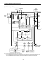
1. FUNCTIONS AND CONFIGURATION
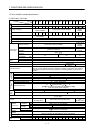
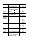
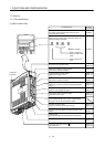
Function Description
(Note)
Control mode
Reference
Position smoothing Speed can be increased smoothly in response to input pulse. P Parameter No.PB03
S-pattern acceleration/
deceleration time constant
Speed can be increased and decreased smoothly. S, T Parameter No.PC03
Regenerative option
Used when the built-in regenerative resistor of the servo
amplifier does not have sufficient regenerative capability for
the regenerative power generated.
P, S, T Section 12.2
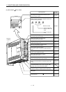
Brake unit
Used when the regenerative option cannot provide enough
regenerative power.
Can be used with the MR-J3-500A
MR-J3-700A.
P, S, T Section 12.3
Return converter
Used when the regenerative option cannot provide enough
regenerative power.
Can be used with the MR-J3-500A
MR-J3-700A.
P, S, T Section 12.4
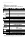
Alarm history clear Alarm history is cleared. P, S, T Parameter No.PC18
Restart after instantaneous
power failure
If the input power supply voltage had reduced to cause an
alarm but has returned to normal, the servo motor can be
restarted by merely switching on the start signal.
S Parameter No.PC22
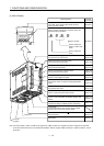
Command pulse selection
Command pulse train form can be selected from among three
different types.
P Section 5.1.12
Input signal selection
(Device settings)
Forward rotation start, reverse rotation start, servo-on (SON)
and other input device can be assigned to certain pins of the
CN1 connectors.
P, S, T
Parameters
No.PD03 to PD08,
PD10 to PD12
Output signal selection
(Device settings)
Trouble (ALM), dynamic brake interlock (MBR) and other
output device can be assigned to certain pins of the CN1
connectors.
P, S, T
Parameters
No.PD13 to PD16,
PD18
Torque limit Servo motor torque can be limited to any value. P, S
Section 3.6.1 (5)
Section 5.1.11
Speed limit Servo motor speed can be limited to any value. T
Section 3.6.3 (3)
Parameter
No.PC05 to PC11
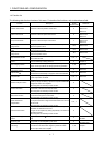
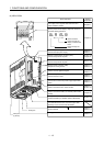
Status display Servo status is shown on the 5-digit, 7-segment LED display P, S, T Section 6.3
External I/O signal display
ON/OFF statuses of external I/O signals are shown on the
display.
P, S, T Section 6.7
Output signal (DO)
forced output
Output signal can be forced on/off independently of the servo
status.
Use this function for output signal wiring check, etc.
P, S, T Section 6.8
Automatic VC offset
Voltage is automatically offset to stop the servo motor if it does
not come to a stop at the analog speed command (VC) or
analog speed limit (VLA) of 0V.
S, T Section 6.4
Test operation mode
JOG operation, positioning operation, motor-less operation,
DO forced output and program operation.
However, MR Configurator is necessary for positioning
operation and program operation.
P, S, T Section 6.9
Analog monitor output Servo status is output in terms of voltage in real time. P, S, T Parameter No.PC14
MR Configurator
Using a personal computer, parameter setting, test operation,
status display, etc. can be performed.
P, S, T Section 12.8
Alarm code output
If an alarm has occurred, the corresponding alarm number is
output in 3-bit code.
P, S, T Section 9.1
Amplifier diagnosis function
The DI/DO signals, analog monitor input I/F, analog monitor
output, command pulse I/F and encoder pulse output are
checked. The diagnosis cable (MR-J3ACHECK) and MR
Configurator are necessary for this function.
P, S, T Section 12.8 (2)(C)
Note. P: Position control mode, S: Speed control mode, T: Torque control mode
P/S: Position/speed control change mode, S/T: Speed/torque control change mode, T/P: Torque/position control change mode