


15 - 42
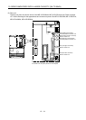
15. SERVO AMPLIFIERS WITH A LARGE CAPACITY
(
30k TO 55kW
)
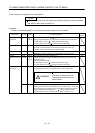
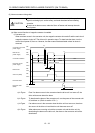
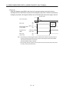
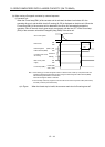
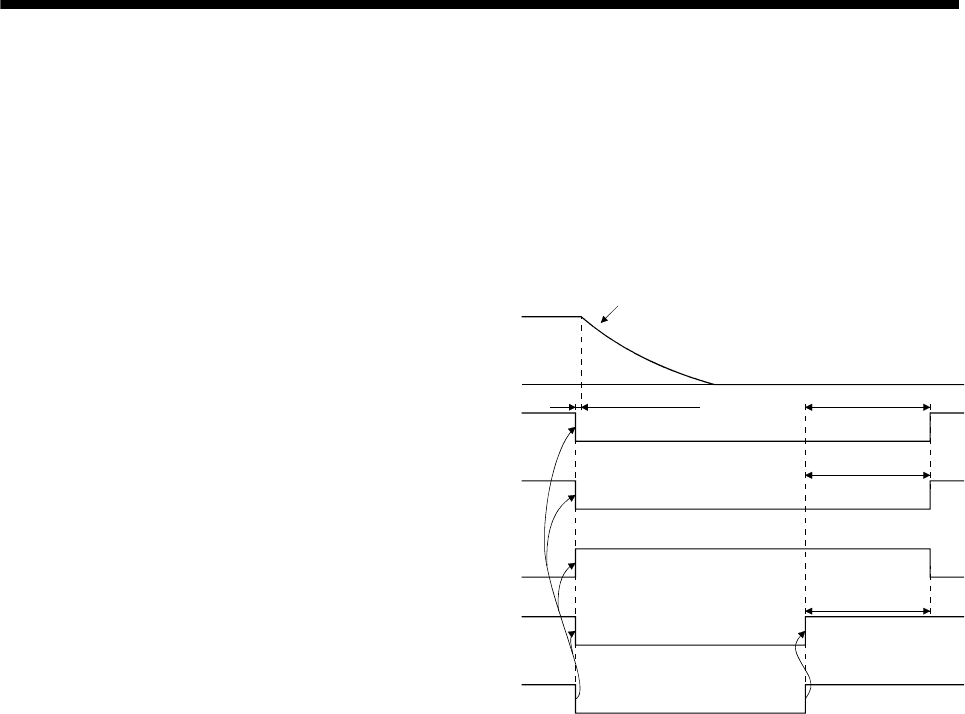
(3) Forced stop (EM1) ON/OFF timing chart
(a) When control function of magnetic controller is enabled
1) Converter unit
When the forced stop (EM1) is made valid in the converter unit, the magnetic contactor is turned off
and the main circuit power supply is shut off. The drive unit in operation stops, and Main circuit off
warning (AL.E9) appears. When the forced stop (EM1) is deactivated in the converter unit, the
magnetic contactor is turned on, the main circuit power is supplied, and then the drive unit
automatically resumes the operation.
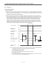
(Note 2)
Dynamic brake
Electromagnetic
brake interlock (MBR)
Base circuit
Servo motor speed
Converter main circuit
off warning
Existence
Nothing
Main circuit power
supply
ON
OFF
Forced stop (EM1)
Invalid (ON)
Valid (OFF)
(3s)
(3s)
(3s)
ON
OFF
(Note 1)
ON
OFF
b)
b)
a)
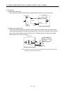
Note 1. When setting up an electromagnetic brake at customer's side, make up a sequence which
will operate the electromagnetic brake as follow using the electromagnetic brake interlock
(MBR).
ON: Electromagnetic brake is not activated.
OFF: Electromagnetic brake is activated
2. There is delay caused by magnetic contactor built into the external dynamic brake (about
50ms) and delay caused by the external relay.
a) in Figure
b) in Figure
As the forced stop (EM1) is disabled for the converter unit, the main circuit power
supply turns on.
After charging the main circuit condenser is completed, base circuit and
electromagnetic brake interlock turn on.