


15 - 11
15. SERVO AMPLIFIERS WITH A LARGE CAPACITY
(
30k TO 55kW
)
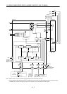
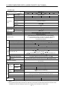
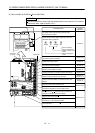
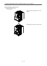
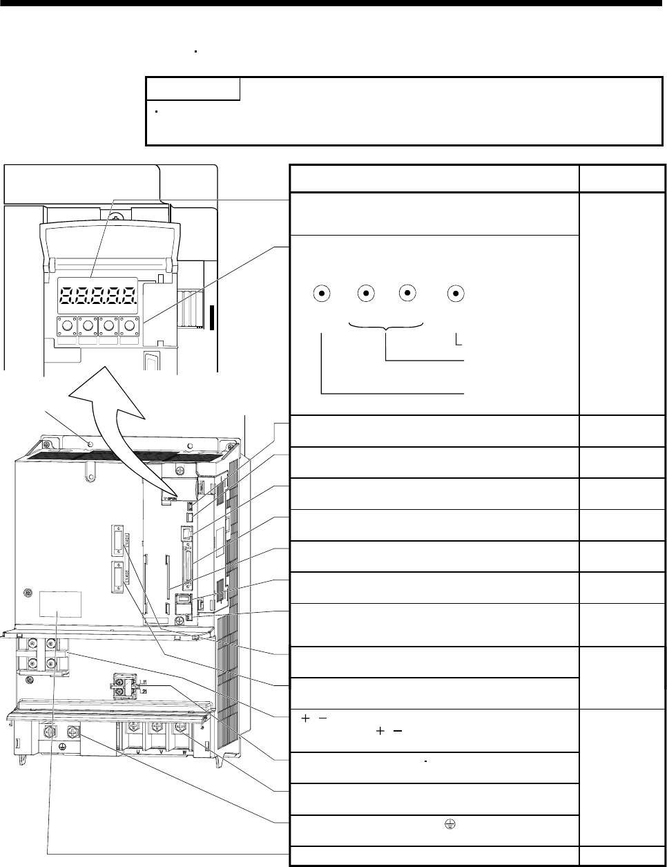
(2) Drive unit (MR-J3-DU30KA4
MR-J3-DU37KA4)
POINT
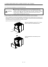
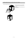
The servo amplifier is shown with the terminal block cover removed. For removal
of the front cover, refer to section 15.1.7.
MODE UP DOWN SET
Fixed part
(4 place)
Cooling fan
Rating plate
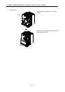
Display
The 5-digit, seven-segment LED shows the servo
status and alarm number.
USB communication connector (CN5)
Connect the personal computer.
Analog monitor connector (CN6)
Outputs the analog monitor.
RS-422 communication connector (CN3)
Connect the personal computer.
I/O signal connector (CN1)
Used to connect digital I/O signals.
Encoder connector (CN2)
Used to connect the servo motor encoder.
Battery connector (CN4)
Used to connect the battery for absolute position data
backup.
Section 15.1.4
Section 15.3.3
Name/Application
Detailed
explanation
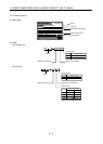
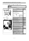
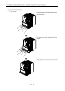
Operation section
Used to perform status display, diagnostic, alarm and
parameter setting operations.
MODE UP
DOWN
SET
Chapter 6
Used to set data.
Used to change the
display or data in each
mode.
Used to change the
mode.
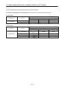
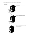
Converter unit connectors (CN40A)
Connect to CN40 of the converter unit.
Converter unit connectors (CN40B)
Connect the termination connector (MR-J3-TM).
L L terminals (TE2)
Connect to the L L terminals of the converter unit
using the connection conductors supplied.
Control circuit terminal L
11
L
21
(TE3)
Supply control circuit power.
Motor power supply terminals (TE1)
Connect to U, V, W of the servo motor.
Protective earth (PE) terminal ( )
Ground terminal.
Section 12.8
Section 3.2
Section 3.4
Section 12.8
Chapter 13
Section 3.2
Section 3.4
Section 14.3
Section 3.4
Section 12.1
Section 12.9
Chapter 14
Section 15.3.2
Battery holder
Contains the battery for absolute position data backup.