


3 - 65
3. SIGNALS AND WIRING
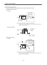
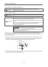
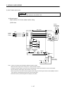
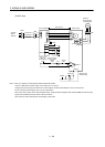
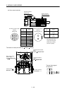
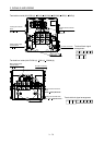
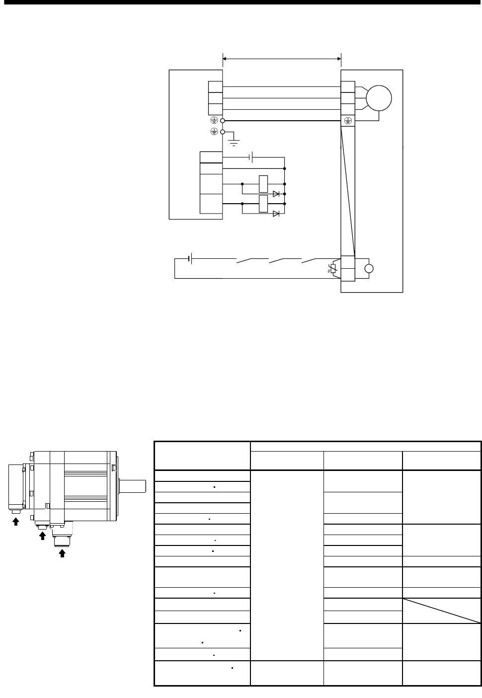
2) When the power supply connector and the electromagnetic brake connector are shared.
Servo motorServo amplifier
24VDC power
supply for
electromagnetic
brake
50m or less
RA1
Electromagnetic
brake interlock
(MBR)
RA2
M
U
V
W
U
V
W
24VDC
ALM
DOCOM
DICOM
MBR
CN1
(Note 1)
B1
B2
B
RA1
RA2
(Note 3)
RA3
Trouble
(ALM)
(Note 2)
Note 1. There is no polarity in electromagnetic brake terminals B1 and B2.
2. When using a servo motor with an electromagnetic brake, assign the
electromagnetic brake interlock (MBR) to external output signal in the parameters
No.PA04, PD13 to PD16 and PD18.
3. Shut off the circuit by interlocking with the emergency stop switch.
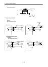
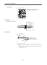
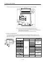
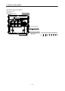
(b) Connector and signal allotment
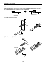
The connector fitting the servo motor is prepared as optional equipment. Refer to section 12.1. For
types other than those prepared as optional equipment, refer to chapter 3 in Servo Motor Instruction
Manual (Vol. 2) to select.
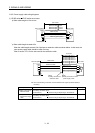
a
c
b
Servo motor
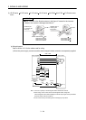
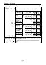
Servo motor side connectors
Encoder Power supply
Electromagnetic
brake
HF-SP52(4) to 152(4)
MS3102A18-10P
CM10-R2P
(DDK)
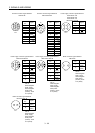
HF-SP51 81
HF-SP202(4) to 502(4)
MS3102A22-22P
HF-SP121 to 301
HF-SP421 702(4) CE05-2A32-17PD-B
HC-RP103 to 203 CE05-2A22-23PD-B
The connector for
power is shared
HC-RP353 503 CE05-2A24-10PD-B
HC-UP72 152 CE05-2A22-23PD-B
HC-UP202 to 502 CM10-R10P CE05-2A24-10PD-B MS3102A10SL-4P
HC-LP52 to 152
(DDK)
CE05-2A22-23PD-B
The connector for
power is shared
HC-LP202 302 CE05-2A24-10PD-B MS3102A10SL-4P
HA-LP502 CE05-2A24-10PD-B
HA-LP702 CE05-2A32-17PD-B
HF-JP53(4) to 203(4)
3534 5034
MS3102A18-10P
CM10-R2P
(DDK)
HF-JP353 503 MS3102A22-22P
HF-JP11K1M (4)
15K1M (4)
MS3102A20-29P MS3102A32-17P MS3101A10SL-4P