


4 - 7
4. STARTUP
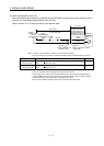
4.2.5 Actual operation
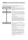
Start actual operation after confirmation of normal operation by test operation and completion of the
corresponding parameter settings. Perform a home position return as necessary.
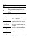
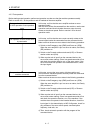
4.2.6 Trouble at start-up
CAUTION
Excessive adjustment or change of parameter setting must not be made as it will
make operation instable.
POINT
Using the optional MR Configurator, you can refer to unrotated servo motor
reasons, etc.
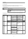
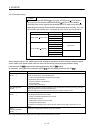
The following faults may occur at start-up. If any of such faults occurs, take the corresponding action.
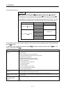
(1) Troubleshooting
No. Start-up sequence Fault Investigation Possible cause Reference
1 Power on LED is not lit.
LED flickers.
Not improved if connectors CN1,
CN2 and CN3 are disconnected.
1. Power supply voltage fault
2. Servo amplifier is faulty.
Improved when connectors CN1
is disconnected.
Power supply of CN1 cabling is
shorted.
Improved when connector CN2 is
disconnected.
1. Power supply of encoder
cabling is shorted.
2. Encoder is faulty.
Improved when connector CN3 is
disconnected.
Power supply of CN3 cabling is
shorted.
Alarm occurs. Refer to section 9.2 and remove cause. Section 9.2
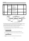
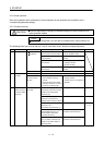
2 Switch on servo-
on (SON).
Alarm occurs. Refer to section 9.2 and remove cause. Section 9.2
Servo motor shaft is
not servo-locked
(is free).
1. Check the display to see if the
servo amplifier is ready to
operate.
2. Check the external I/O signal
indication (section 6.7) to see if
the servo-on (SON) is ON.
1. Servo-on (SON) is not input.
(Wiring mistake)
2. 24VDC power is not supplied to
DICOM.
Section 6.7
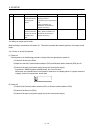
3 Enter input
command.
(Test operation)
Servo motor does
not rotate.
Check the cumulative command
pulse on the status display or MR
Configurator (section 6.3).
1. Wiring mistake
(a) For open collector pulse
train input, 24VDC power is
not supplied to OPC.
(b) LSP and LSN are not on.
2. Pulse train is not input from the
controller.
3. Electromagnetic brake is
operating.
Section 6.3
Check if the Ready (RD) is ON.
Check the parameter No.PA13
(command pulse input form)
setting.
Check if the Electromagnetic
brake interlock (MBR) is ON.
Servo motor run in
reverse direction.
Check the cumulative command
pulse on the status display or MR
Configurator.
1. Mistake in wiring to controller.
2. Mistake in setting of parameter
No.PA14.
Chapter 5
Check the parameter No.PA14
(rotation direction selection)
setting.