


16 - 5
16. PARAMETER UNIT (MR-PRU03)
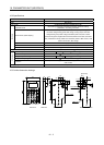
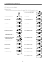
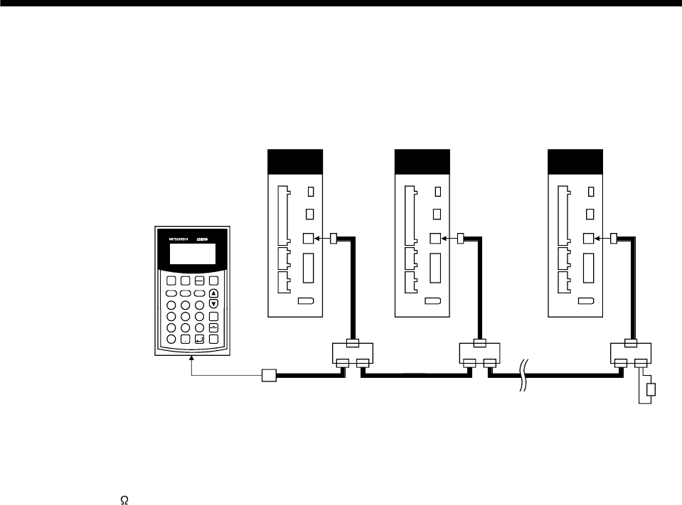
16.4.2 Multidrop connection
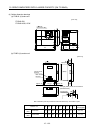
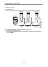
(1) Configuration diagram
Up to 32 axes of servo amplifiers (drive units) from stations 0 to 31 can be operated on the same bus.
(
Note 3
)
(Note 2)
Servo amplifier
(drive unit)
Servo amplifier
(drive unit)
Servo amplifier
(drive unit)
(Note 2)
(Note 1)
(Note 2)
(Note 1) (Note 1)
(Note 2) (Note 2)
CN3 CN3 CN3
PRU03
MON
DATA
PARAM
ALM/
DGN
TEST
Fn SHIFT ESC
7
8
9
D
EF
4
5
6
A
B
C
1
23
0
1STEP
STOP
RESET
REV
FWD
Parameter unit
(MR-PRU03)
(Note 2)
Note 1. The BMJ-8 (Hakko Electric Machine Works) is recommended as the branch connector.
2. Use the 10BASE-T cable (EIA568-compliant), etc.
3. The final axis must be terminated between RDP (pin No.3) and RDN (pin No.6) on the receiving side (servo amplifier (drive
unit)) with a 150
resistor.