


3 - 5
3. SIGNALS AND WIRING
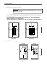
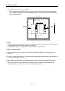
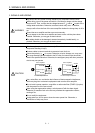
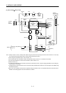
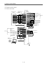
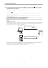
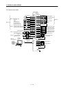
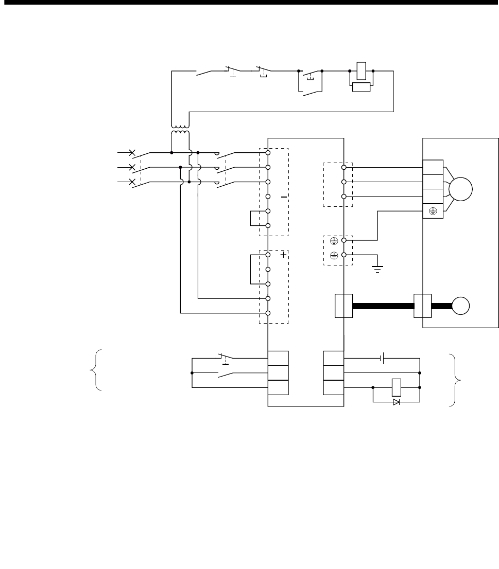
(4) MR-J3-60A4 to MR-J3-200A4
P
N
(Note 4)
SON
EMG
L
1
L
2
L
3
3-phase
380 to
480VAC
ALM
P
1
P
2
DICOM
DOCOM
L
11
L21
D
C
U
V
W
(Note 1)
(Note 2)
CNP1
CNP3
PE
CNP2
U
V
W
M
Motor
Encoder
CN2
(Note 3)
Encoder cable
(Note 5)
DOCOM
CN1 CN1
24VDC
Trouble
(Note 4)
MCNFB
RA
Servo motorServo amplifier
Emergency stop (Note 7)
Servo-on
(Note 8)
Trouble
RA
Emergency stop
OFF
MC
ON
MC
SK
(Note 7)
(Note 6)
Stepdown
transformer
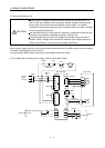
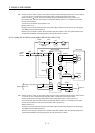
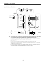
Note 1. Always connect P1 and P2. (Factory-wired.) When using the power factor improving DC reactor, refer to section
12.13. Use only one of power factor improving DC reactor or power factor improving AC reactor.
2. Always connect P and D. (Factory-wired.) When using the regenerative option, refer to section 12.2.
3. For encoder cable, use of the option cable is recommended. Refer to section 12.1 for selection of the cable.
4. For the sink I/O interface. For the source I/O interface, refer to section 3.8.3.
5. Refer to section 3.10.
6. Stepdown transformer is required for coil voltage of magnetic contactor more than 200V class.
7. Configure the circuit to shut down the main circuit power supply simultaneously with the turn off of emergency
stop (EMG) using the external sequence.
8. Be sure to use a magnetic contactor with an operation delay time of 80ms or less. The operation delay time is
the time interval between current being applied to the coil until closure of contacts.