


14 - 52
14. ABSOLUTE POSITION DETECTION SYSTEM
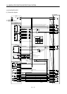
Note 1. For the dog type home position return. Need not be connected for the data set type home position return.
2. For the dog type home position return, connect a QD75 deviation counter clearing signal cable. For the data set type home
position return, connect a cable to the output module of the programmable controller.
3. This circuit is provided for your reference.
4. The electromagnetic brake output should be controlled via a relay connected to the programmable controller output.
5. Refer to section 3.8.2 (3)(b) and Type QD75P/QD75D Positioning Module User’s Manual when connecting to QD75P.
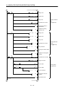
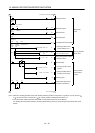
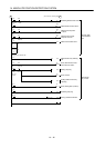
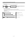
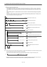
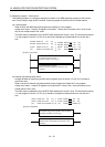
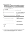
(2) Sequence program example
(a) Conditions
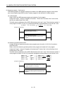
The ABS data is transmitted using the leading edge of the servo-on switch as a trigger.
1) When the servo-on switch and power supply GND are shorted, the ABS data is transmitted at power-
on of the servo amplifier or on the leading edge of the RUN signal after a PC reset operation (PC-
RESET). The ABS data is also transmitted when an alarm is reset or when an emergency stop is
reset.
2) An ABS checksum error is caused (Y3AON) if checksum inconsistency is found in transferred data.
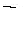
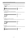
3) The following time periods are measured. If the ON/OFF state does not change within the specified
time, the ABS communication error occurs change within the specified time, the ABS communication
error occurs (Y3A ON).
ON period of ABS transfer mode (Y31)
ON period of ABS request (Y32)
OFF period of reading to send ABS data (X22)
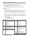
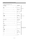
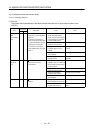
(b) Device list
X input contact Y output contact
X20 ABS transmission data bit 0/Positioning completion Y30 Servo-on
X21 ABS transmission data bit 1/zero speed detection Y31 ABS transfer mode
X22 ABS transmission data ready/Torque limiting Y32 ABS request
X23 Servo alarm Y33 Alarm reset
X24 Alarm reset switch Y34
(Note 2)
Electromagnetic brake output
X25 Servo emergency stop Y35
(Note 1)
Clear
X26 Servo-on switch Y38 Servo alarm
X27 Home position return start switch Y39 ABS communication error
X28 Operation mode I Y3A ABS checksum error
X29 Operation mode II
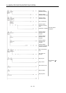
D register M contact
D0 Number of retries M0 End of error reset
D9 Home position address: Lower 16 bits M10 Preparation completion
D10 Home position address: Upper 16 bits M11 Servo-on request
D100 to D104 For absolute position restoration dedicated M12 Absolute position restoration instruction PLS
instruction M13 Absolute position restoration memory
T timer M14 Error flag output
T0 Retry wait timer M15 Sum check NG
T10
(Note 1)
Clear (CR) ON timer M16 Retry flag
M17 Retry flag reset request
M20
(Note 1)
Clear (CR) ON timer request
M21
(Note 1)
Data set type home position return request
M100 to M101 For absolute position restoration dedicated
instruction
C counter
C0 Retry counter
Note 1. Required for data set type home position return.
2. Required for electromagnetic brake output.