


12 - 52
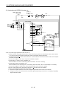
12. OPTIONS AND AUXILIARY EQUIPMENT
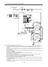
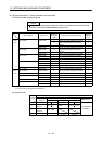
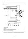
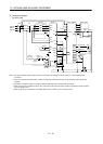
(2) Connection example
P/N/
Ready
NCP
5m or less
RDY output
(Note 2)
BC
Power factor improving
AC reactor (Note 8)
SON
(Note 6)
Power
supply
RRX
R
SX
S
TX
T
R/L
1
S/L2
T/L
3
B
C
EMG
CN1
DOCOM
DICOM
ALM
CN1
24VDC
Trouble
Servo-on
(Note 3)
(Note 3)
DOCOM
Emergency stop
(Note 7)
(Note5)
Power regenerative
converter FR-RC-(H)
FR-RC-(H)
B
C
Alarm
output
A
RA
ALM
RA
MCNFB
Operation ready
OFF
MC
ON
MC
EMG (Note 7)
SK
Servo amplifier
(Note 4)
P
2P1
RDY
SE
(Note 1)
Phase detection
terminals
L
11
L21
L1
L2
L
3
Note 1. When not using the phase detection terminals, fit the jumpers across RX-R, SX-S and TX-T. If the jumpers remain removed, the
FR-RC-(H) will not operate.
2. When using servo amplifier of 5kW and 7kW, always remove the lead of built-in regenerative resistor connected to P terminal
and C terminal.
3. This diagram is for sink I/O interface. Refer to section 3.8.3 for source I/O interface.
4. Between P
1
and P
2
(P
1
and P for 11kW to 22kW) is connected by default.
5. Stepdown transformer is required for coil voltage of magnetic contactor more than 200V class in 400V class servo amplifiers.
6. Refer to section 1.3 for the power supply specification.
7. Configure the circuit to shut down the main circuit power supply simultaneously with the turn off of emergency stop (EMG) using
the external sequence.
8. For selection of power factor improving AC reactors, refer to "Power Regeneration Converter FR-RC Instruction Manual
(IB(NA)66330)".