


3 - 56
3. SIGNALS AND WIRING
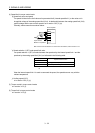
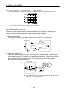
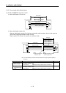
Note 1. P: Position control mode S: Speed control mode T: Torque control mode
2. For the differential line driver pulse train input. For the open collector pulse train input, make the following connection.
DOCO 46
OPC 12
20
47
PP 10
PG 11
NP 35
NG 36
DICOM
DOCOM
24VDC
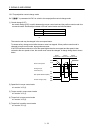
3. For the sink I/O interface. For the source I/O interface, refer to section 3.8.3.
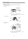
3.8.2 Detailed description of interfaces
This section provides the details of the I/O signal interfaces (refer to the I/O division in the table) given in
section 3.5. Refer to this section and make connection with the external equipment.
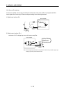
(1) Digital input interface DI-1
Give a signal with a relay or open collector transistor. Refer to section 3.8.3 for source input.
SON,
etc.
Servo amplifier
Switch
Approx. 5mA
For transistor
DICOM
V
CES 1.0V
I
CEO
100
A
TR
24VDC 10
300m
A
Approx. 5.6k
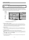
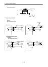
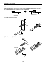
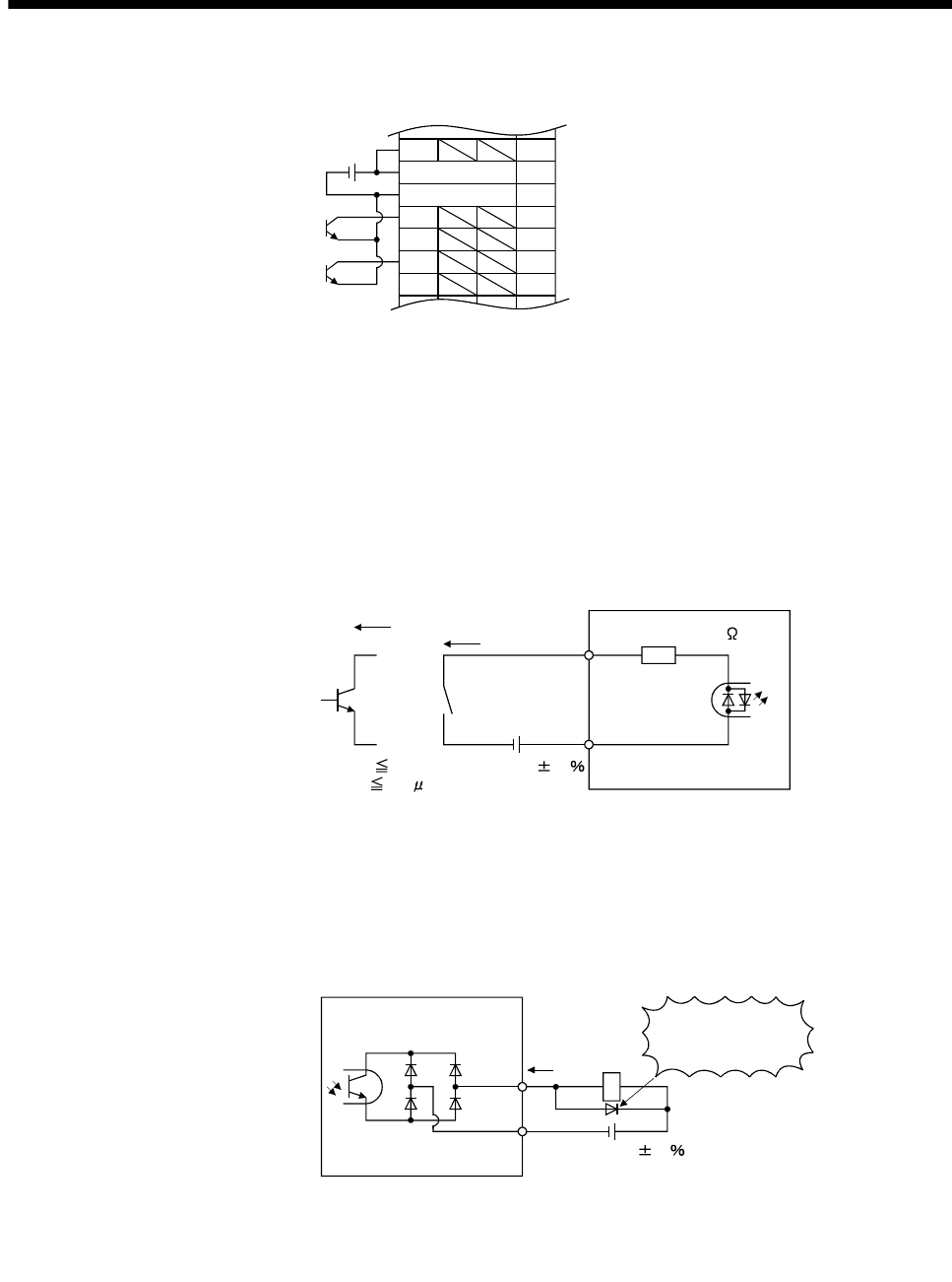
(2) Digital output interface DO-1
A lamp, relay or photocoupler can be driven. Install a diode (D) for an inductive load, or install an inrush
current suppressing resistor (R) for a lamp load. (Rated current: 40mA or less, maximum current: 50mA or
less, inrush current: 100mA or less) A maximum of 2.6V voltage drop occurs in the servo amplifier.
Refer to section 3.8.3 for the source output.
(Note)
Servo amplifier
ALM,
etc.
Load
DOCOM
If polarity of diode is
reversed, servo
amplifier will fail.
24VDC 10
300mA
Note. If the voltage drop (maximum of 2.6V) interferes with the relay operation, apply high
voltage (up to 26.4V) from external source.