


3 - 76
3. SIGNALS AND WIRING
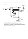
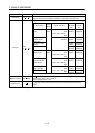
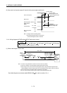
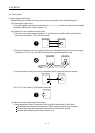
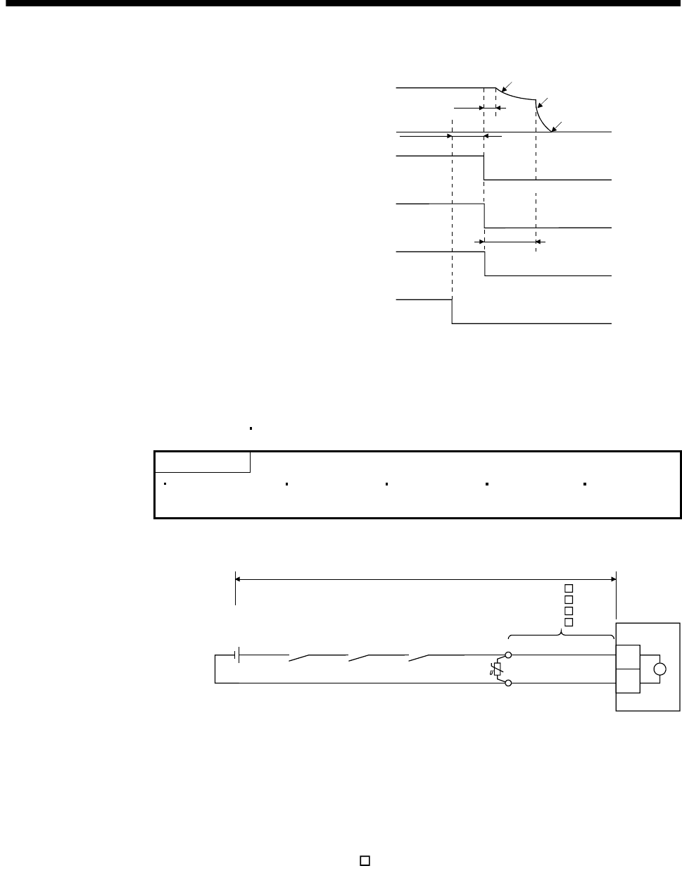
(5) Only main circuit power supply off (control circuit power supply remains on)
Servo motor speed
ON
OFF
Base circuit
Electromagnetic
brake interlock
(MBR)
(Note 2) ON
OFF
Trouble (ALM)
No (ON)
Yes (OFF)
ON
OFF
Main circuit power
supply
Dynamic brake
Dynamic brake
Electromagnetic brake
Electromagnetic brake
Electromagnetic brake
operation delay time
(10ms)
(Note 1)
15ms or longer
Note 1. Changes with the operating status.
2. ON: Electromagnetic brake is not activated.
OFF: Electromagnetic brake is activated.
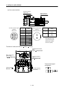
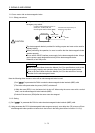
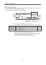
3.11.4 Wiring diagrams (HF-MP series HF-KP series servo motor)
POINT
For HF-SP series HC-RP series HC-UP series HC-LP series HF-JP series
servo motors, refer to section 3.10.2 (2).
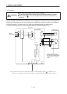
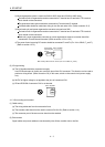
(1) When cable length is 10m or less
10m or less
Electromagnetic
brake interlock
(MBR)
AWG20
AWG20
(Note 1)
B1
B2
Trouble
(ALM)
Servo motor
B
(Note 4)
(Note 2)
MR-BKS1CBL M-A1-L
MR-BKS1CBL M-A2-L
MR-BKS1CBL M-A1-H
MR-BKS1CBL M-A2-H
24VDC power
supply for
electromagnetic
brake
(Note 5)
(Note 3)
Note 1. Connect a surge absorber as close to the servo motor as possible.
2. There is no polarity in electromagnetic brake terminals (B1 and B2).
3. When using a servo motor with an electromagnetic brake, assign the electromagnetic brake
interlock (MBR) to external output signal in the parameters No.PA04, PD13 to PD16 and PD18.
4. Shut off the circuit by interlocking with the emergency stop switch.
5. Do not use the 24VDC interface power supply for the electromagnetic brake.
When fabricating the motor brake cable MR-BKS1CBL
M-H, refer to section 12.1.4.