


5 - 49
5. PARAMETERS
No. Symbol Name and function
Initial
value
Unit
Setting
range
Control mode
Position Speed Torque
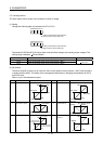
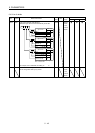
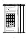
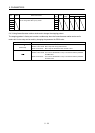
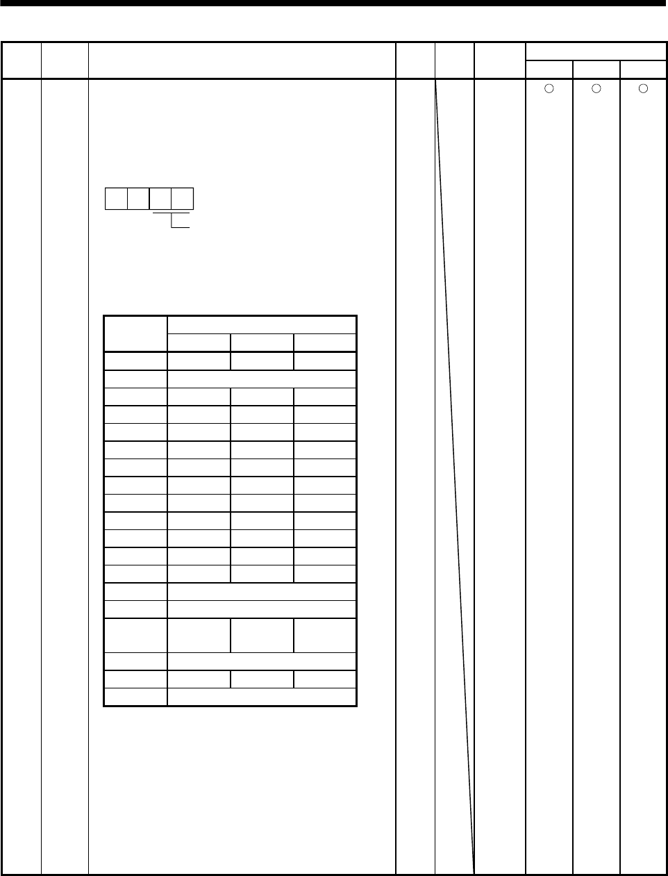
PD13 *DO1 Output signal device selection 1 (CN1-22)
Any output signal can be assigned to the CN1-22 pin.
In the initial setting, INP is assigned in the position control
mode, and SA is assigned in the speed control mode.
Note that the device that can be assigned changes
depending on the control mode.
Select the output device of the CN1-22 pin.
00
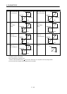
The devices that can be assigned in each control mode are
those that have the symbols indicated in the following table.
If any other device is set, it is invalid.
0004h Refer to
name
and
function
column.
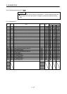
Setting
Control modes (Note 1)
P S T
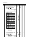
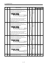
00 Always OFF Always OFF Always OFF
01 For manufacturer setting (Note 2)
02 RD RD RD
03 ALM ALM ALM
04 INP SA Always OFF
05 MBR MBR MBR
06 DB DB DB
07 TLC TLC VLC
08 WNG WNG WNG
09 BWNG BWNG BWNG
0A Always OFF SA SA
0B Always OFF Always OFF VLC
0C ZSP ZSP ZSP
0D For manufacturer setting (Note 2)
0E For manufacturer setting (Note 2)
0F CDPS
Always
OFF
Always
OFF
10 For manufacturer setting (Note 2)
11 ABSV Always OFF Always OFF
12 to 3F For manufacturer setting (Note 2)
Note 1. P: Position control mode
S: Speed control mode
T: Torque control mode
2. For manufacturer setting. Never set this value.
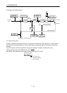
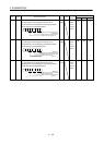
When "Valid (ABS transfer by DI0)" has been selected for
the absolute position detection system in parameter
No.PA03, the CN1-22 pin is set to the ABS transmission
data bit 0 (ABSB0) in the ABS transfer mode only. (Refer to
section 14.7.)