


12xx-Slots
121x-Lines
1213-T1/E1 Card Setup
DSX Software Manual System Options: 1001-1702 ◆ 617
System
1001-1702
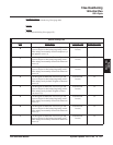
1213-03: Transmit Pulse Amplitude
(Tx Pulse Ampl.)
This option controls the amplitude (strength) of the T1 signals transmitted by the PCB to the telco smart jack
or your CSU (if used).
Entries 0-4 correspond to the distance from the T1 PCB to either the telco’s smart jack or your CSU (depend-
ing on your installation). The T1 PCB automatically adjusts the signal amplitude based on your entry.
You can alternately use entries 5-7 to make fixed attenuation entries. If connected to a CSU, set your attenu-
ation to match the requirements of the CSU. If your T1 PCB is connected directly to the telco’s smart jack,
the telco will tell you if any attenuation is required.
This option does not apply to E1 circuits.
Features
• T1 Lines (page 338)
Intr
aMail Features
• None
Options
• 1 for 0-133 feet (0 dB)
• 2 for 133-266 feet
• 3 for 266-399 feet
• 4 for 399-533 feet
• 5 for 533-655 feet
• 6 for -7.5 dB
• 7 for -15 dB
• 8 for -22.5 dB
Default
• 1
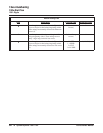
1213-04: Framer Type
(ESF/CRC4)
Use this option to set the Framer Type used by the PCB.
If this option is enabled:
❥ T1 circuits use ESF (Extended Super Frame) mode. This is a 24-Frame mode which provides ABCD sig-
naling bits and additional diagnostics).
❥ E1 circuits use CRC-4 16-Frame Multiframe mode.
If this option is disabled:
❥ T1 circuits use D3/D4 (12-Frame Multiframe mode which supports AB signaling bits only).
❥ E1 circuits do not use CRC4 mode.
Always set this option for compatibility with the connected telco. Normally, T1 circuits use ESF.
Features
• T1 Lines (page 338)
IntraMail Features
• None
Options
• No (0) - Disabled
• Yes (1) - Enabled