


3
- 20
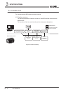
3.4 I/O Signals for Programmable Controller CPU
3.4.2 I/O signals details
3
SPECIFICATIONS
(From the previous page)
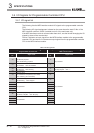
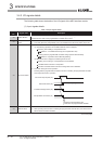
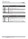
(2) Output signals details
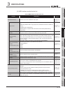
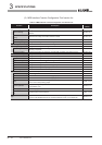
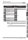
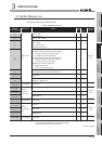
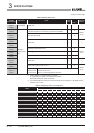
Table 3.13 Input signals details
Device
No.
Signal name Description
X16
Access target CPU
error
(1) Turns ON when an error occurs in communications with the access target CPU.
(2) When this device is ON, the error code is stored into the Access target CPU setting status area
(Buffer memory address: 4000 to 4071).
(3) Turns OFF when the Error clear request (Y10) is turned ON.
X1C Another error
(1) Turns ON when an error not corresponding to X11, X12, or X16 occurs.
(2) When this device is ON, the error code is stored into the Error log area (Buffer memory
address: 150 to 247).
(3) Turns OFF when the Error clear request (Y10) is turned ON. (Only in case of a module
continuation error)
X1F
Watchdog timer
error
Turns ON when a watchdog timer error occurs.
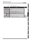
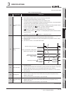
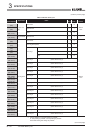
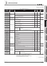
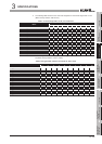
Table 3.14 Output signals details
Device
No.
Signal name Description
Y2
File access stop
request
(1) Turns ON when file access is stopped.
(2) For ON/OFF timing, refer to the description of X2.
Y10 Error clear request
(1) By turning ON during a module continuation error (ERR. LED: ON) turns OFF the ERR. LED
and X10, X11, X16, and X1C.
During a module stop error (ERR. LED: flashing), turning this device ON does not turn OFF the
ERR. LED.
(2) Clears the Current error area (Buffer memory address: 140 to 145).
Clears the latest error code displayed on [System monitor] of GX Developer. ( Section
10.1.3 System monitor)