1 - 53
1 OVERVIEW
Special register list (continued)
No. Name Meaning Details
Set by
(When set)
Remark
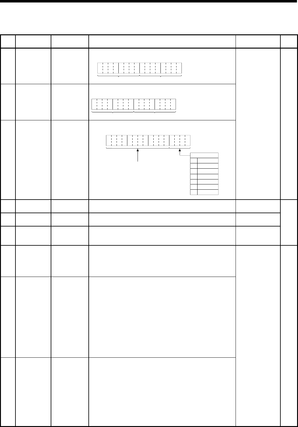
D9026 Clock data
Clock data
(Day, hour)
• Stores the day and hour in BCD.
B15 B12to B11 B8to B7 B4to B3 B0to
Day Hour
Example : 31st, 10 a.m.
H3110
D9027 Clock data
Clock data
(Minute, second)
• Stores the minute and second in BCD.
Example : 35 min., 48 sec.
H3548
B15 B12to B11 B8to B7 B4to B3 B0to
Minute
Second
D9028 Clock data
Clock data
(Day of week)
• Stores the day of the week in BCD.
B15 B12to B11 B8to B7 B4to B3 B0to
"0" must be set here.
Day of week
0
1
2
3
4
5
6
Sunday
Monday
Tuesday
Wednesday
Thursday
Friday
Saturday
Example :
Friday
H0005
S/U(Request)
D9060
Diagnostic error
reset error No.
Error No. of
releasing an error
• Error No. of canceling error is stored. U
D9061 Multiple CPU No. Multiple CPU No. • CPU No. of the self CPU is stored. S(Initial processing)
D9104
Servo parameter
read request axis
No.
Servo parameter
read axis No.
• Axis No. of servo amplifier which begins to read servo parameter is setting.
Q173CPU(N) : 1 to 32 (Axis1 to 32)
Q172CPU(N) : 1 to 8 (Axis1 to 8)
U
New
(Note)
D9182
D9183
Test mode
request error
It is operating in
requirement error
occurrence of the
test mode, axis
information
• Each axis is stopping : 0/Operating : 1, information is stored as a bit data.
D9182 : b0 to b15(Axis 1 to Axis 16)
D9183 : b0 to b15(Axis 17 to Axis 32)
D9184
Motion CPU WDT
error cause
Error meaning of
WDT error occurs
The following error codes are stored in D9184.
1 : S/W fault 1
2 : Operation cycle over
3 : Q bus WDT error
4 : WDT error
30 : Information processor H/W error
201 to 215 : Q bus H/W fault
250 to 253 : Servo amplifier interface H/W fault
300 : S/W fault3
301 : 15 CPSTART instructions of 8 or more points were started
simultaneously.
302 : During ROM operation, system setting data, program and
parameter written to internal FLASH ROM are fault.
D9185
D9186
D9187
Manual pulse
generator axis
setting error
Manual pulse
generator axis
setting error
information
• Contents of the manual pulse generator axis setting error is stored when the
manual pulse generator axis setting error flag(M9077) turn on.
(Normal : 0/Setting error : 1)
D9185 : The manual pulse generator axis setting error is stored in b0 to b2
(P1 to P3).
The smoothing magnification setting is stored in b3 to b5 (P1 to
P3).
D9186 : One pulse input magnification setting error is stored in b0 to b15
(axis 1 to axis 16).
D9187 : One pulse input magnification setting error is stored in b0 to b15
(axis 17 to axis 32).
S(Occur an error)
(Note) : It adds newly at the Motion controller Q series.


