


1 - 80
1 OVERVIEW
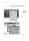
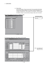
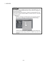
1.5 System Settings
1.5.1 System data settings
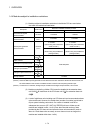
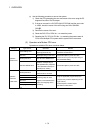
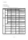
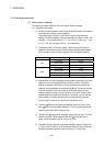
The table below lists the system data items to be set.
Item Setting range Initial value Remark
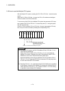
CPU base 2/3/5/8/10/12 slots CPU base : 2 slots
Base setting
Extension base None/2/3/5/8/10/12 slots None
Set the number of slots in the CPU base
or extension base.
Number of Multiple
CPUs
2/3/4 modules 2 modules
Set the total number of Multiple CPUs
including PLC CPU(s).
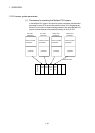
Automatic refresh
setting
Up to 2k words of devices
(D/W/#/M/Y/B) can be set per
CPU for settings 1 to 4.
None
Set the automatic refresh between CPUs
using Multiple CPU shared memory.
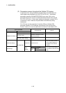
Multiple CPU
setting
Error operation mode
at the stop of CPU
Stop/do not stop all CPUs
upon an error in CPU Nos.
1/2/3/4.
(The setting range varies
depending on the number of
Multiple CPUs installed.)
Stop all CPUs upon
error in CPU Nos.
1/2/3/4
Set whether or not to stop the entire
system when a CPU stop error occurs in
each CPU.
Module arrangement
Within the CPU base and
extension base slots
None
Install the modules controlled by the self
CPU in the CPU base and/or extension
base(s).
Common
system
parameters
Motion slot
setting
Individual module
Varies depending on the
module.
Varies depending on
the module.
Set detailed items for each module
controlled by the self CPU.
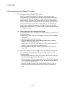
Operation cycle setting
0.8 ms/1.7 ms/3.5 ms/7.1
ms/14.2ms/Auto
Auto Set the operation cycle of motion control.
Operation at STOP to
RUN
M2000 is turned on with switch
(STOP to RUN). M2000
becomes a switch set (STOP
to RUN) + register by single-
unit with turning on.
M2000 is turned on
with switch (STOP to
RUN).
Set the condition in which the PLC ready
flag (M2000) turns on.
Forced stop
(Note)
None/X (PX) (0 to 1FFF)/
M (0 to 8191)
None Set the bit device used for forced stop.
Basic system
setting
Latch range
M (0 to 8191)/B (0 to 1FFF)/F
(0 to 2047)/D (0 to 8191)/W (0
to 1FFF)
None Set the latch range of device memory.
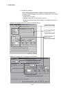
Self CPU installation position setting
Set self CPU/another
CPU/CPU (empty) for slots
0/1/2. (The setting range
varies depending on the
number of Multiple CPUs
installed.)
None
(When two CPUs are
installed, slot 0 is
fixed as the self
CPU.)
Set the installation position of the self
CPU in the CPU base.
Servo amplifier/motor setting
Q173CPU(N):
Up to 2 systems, 32 axes
Q172CPU(N):
Up to 1 system, 8 axes
None
Set the model name, axis No. and other
details for the servo amplifiers and
servomotors.
High-speed read setting
One Q172EX/Q173PX module
and one input module.
None
Set the high-speed read data.
Refer to "Q173CPU(N)/Q172CPU(N)
Motion controller (SV13/SV22)
Programming Manual (Real Mode)" for
the high-speed read function.
Individual
parameters
Battery setting
External battery unused/
External battery used
External battery
unused.
Set whether or not to use an external
battery. If the power supply is down for
one month or longer, data must be
backed up with an external battery.
Refer to "Q173CPU(N)/Q172CPU(N)
User’s Manual" for external battery.
(Note) : The forced stop can also be executed by the forced stop terminal of the servo amplifier besides the forced stop input setting.